ASSIST : Assistive Single Switch Interface - SwitchTester
by Makergo-solutions in Circuits > Assistive Tech
139 Views, 0 Favorites, 0 Comments
ASSIST : Assistive Single Switch Interface - SwitchTester

ASSIST is an interface for jack 3.5mm assisitive switches.
After plugged one, connect the device with an USB C cable to a computer, tablet or smartphone.
It has two functionnalities :
- TESTER : press the switch, the led become green
- HID INTERFACE : A switch press emulate SPACE BAR, KEY ENTER or a mouse click, useful for digital acessibility, AAC purpose and gaming
I created this project to give a course to occupational therapist students. The idea is that they use 3D printing, discover welding, microcontrollers and some programming concepts.So, they learn by doing it and leave with a useful object that they made themselves.
LICENSE :
Creative Commons Attribution-NonCommercial-ShareAlike (CC-BY-NC-SA)
Unless otherwise noted attached to a file, almost all parts of this work, code files, design files, and documentation are licensed under a Creative Commons Attribution-NonCommercial-ShareAlike 4.0 International.
This license allows reusers to distribute, remix, adapt, and build upon the material in any medium or format for noncommercial purposes only, and only so long as attribution is given to the creator. If you remix, adapt, or build upon the material, you must license the modified material under identical terms.
Supplies
- 1 × Adafruit QT PY RP2040
- 1 × Colorful Round Tactile Button Adafruit 1009
- 1 × Mini Protoboard
- 1 × 3.5mm jack breakout
- 1 × 3D Printed parts
Enclosure : 3D Printing
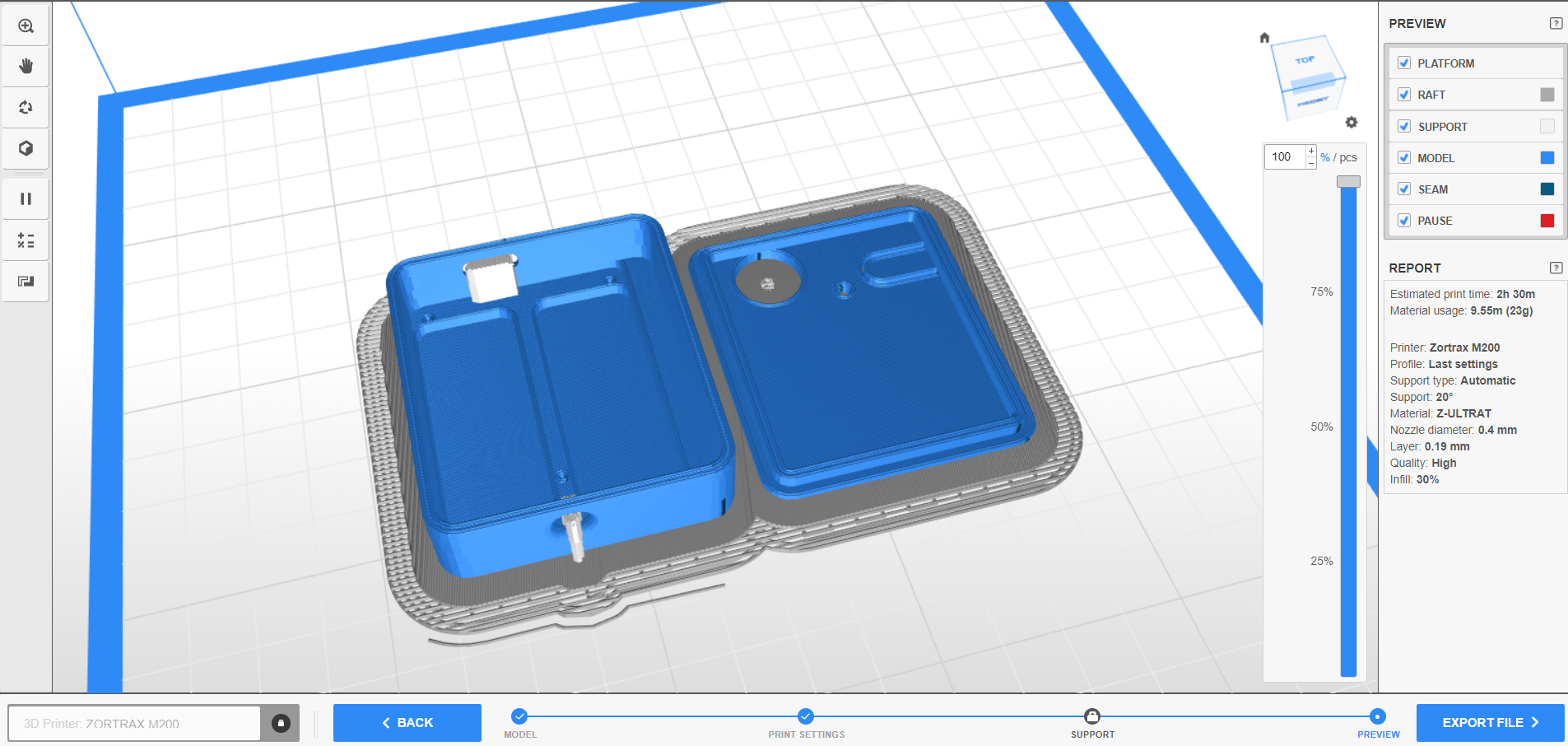
Print the two stl files : base and top
Electronic Assembly


Individually prepare the components :
- 1 × Adafruit QT PY RP2040
- 1 × Colorful Round Tactile Button Adafruit 1009
- 1 × Mini Protoboard
- 1 × 3.5mm jack breakout
- Solder 2*6 headers on the ADAFRUIT QTPY RP2040 (pins A1--TX and RX--GND)

- Solder 2 headers on the 3.5mm jack breakout (pin TIP ans SLEEVE)


- Cut two platsic pins under the tactile switch, cut two pins on the switch


- Cut two wires : 3.5cm and 4cm

Solder the components :
- Solder the ADAFRUIT QTPY RP2040 on the protoboard : B1 to B6 and F1 to F6)

- Solder the tactile switch on the protoboard G1 and G3

- Solder the 3.5mm jack breakout (F11 and E11)

- Connect A3 QTPY's pin to RING02 with the 3.5 cm wire, solder

- Connect GND QTPY's to TIP with the 4cm wire, (J1- J11), solder

Cut of the excess lenght of the pins
Mechanical Assembly
Programing
- While maintain the boot button pressed, plug the QTPY RP2040 in a computer with a USB C CABLE

- A drive name RPI-RP2 appears
- Drag and drop the UF2 file onto this drive
- The QTPY's reboot, the program runs
Use
- Plug a USB C cable from Assist to a computer or a smartphone
- Plug an assistive switch in the jack port of the assist
- When you press the assistive switch the ASSIST emulate a HID Function
- To change the HID mode, press the ASSIST Mode Button, the color's led change
Blue : Spacebar Key
red : Return key
yellow : Left mouse click
green : assistive switch is pressed


