BIOLIGHT - Harmful Algal Bloom Monitoring
by Common9899 in Circuits > Microcontrollers
355 Views, 2 Favorites, 0 Comments
BIOLIGHT - Harmful Algal Bloom Monitoring

Hey, what's up, Guys! Akarsh here from CETech.
In many regions, harmful algal blooms constitute a serious environmental issue. Examples of toxic algal blooms that can have detrimental effects on people's health, aquatic ecosystems, and the economy include red tides, blue-green algae, and cyanobacteria.
These blooms can produce incredibly harmful toxins that can make people and animals unwell or even kill them. They also create dead zones which totally damage the ecosystem.
Supplies
The Items used in this project are:-
- Arm Mbed Studio
- STMicroelectronics STM32CUBEPROG
- Qubitro
- Laser cutter (generic)
- 3D Printer (generic)
Get PCBs for Your Projects Manufactured

You must check out PCBWAY for ordering PCBs online for cheap!
You get 10 good-quality PCBs manufactured and shipped to your doorstep for cheap. You will also get a discount on shipping on your first order. Upload your Gerber files onto PCBWAY to get them manufactured with good quality and quick turnaround time. PCBWay now could provide a complete product solution, from design to enclosure production. Check out their online Gerber viewer function. With reward points, you can get free stuff from their gift shop.
Solution

Chlorophyll can be found in algae which is a photosynthetic organism. A technique called fluorometry is used to measure how much light a material emits when excited using light of different wavelengths(Fluorescence).


(Fluorescence of chlorophyll)
When Chlorophyll is seen under white light, it is green in color. But when it is seen under blue light, it will be red in color as shown in the video below. This helps us to find and detect the presence of Algae. This effect can be observed by the help of this video.
BIOLIGHT is a smart buoy with built-in MCU, Radio, and sensors. It measures the presence of Alage every day and also monitors if the growth is rapid or constant.
Optics
To excite chlorophyll, a 470nm LED light source is used and to measure the emission spectra a spectral sensor only measuring 680nm is used. Additionally, a 530nm long pass filter is used to filter all the light of wavelength below 530nm.

Electronics

BIOLIGHT uses a custom-developed board waveConnect which was specially designed by myself for low-power applications and to harvest solar energy and charge a battery. waveConnect (Open Source and certified by OSHWA) uses LoRa E5 from Seeedstudio which is an MCU and a LoRa Radio. The Seeed LoRa-E5 LoRa Module is a low-cost, ultra-low power, incredibly small, and high-performance LoRa Module. It has STM32WLE5JC, which is an SoC with the combo of LoRa Radio and MCU of ARM Cortex-M4.

Firmware

The firmware of BIOLIGHT is based on ARM's MBED OS. You can flash waveConnect with the excellent Mbed OS framework. The easy way is to use Mbed Studio IDE. The board was developed based on LoRa E5 mini which is available in stm32customtargets. The LoRaWAN firmware is based on the main firmware mbed-os-example-lorawan program.
Interfacing the Sensor
BIOLIGHT uses AS7341 Spectral Sensor Breakout from Adafruit (sensor manufactured by AMS). AS7341 is an 11-channel multi-spectral sensor for color detection and spectral analysis applications. The spectral response is defined in the wavelengths from approximately 350nm to 1000nm. The sensor is i2c based which uses Qwiic/STEMMA QT interfacing system. The codes and other related files for the project can be taken from the Github page of this project that can be accessed from here.

Spectral Responsivity
The default i2c pins of LoRa E5 are PA_15 and PCB_15, which are directly connected to the Qwiic connector in the waveConnect board.
I2C i2c(PA_15, PB_15); // SDA pin, SCL pin
The light source (Blue LED) is controlled by using pin PB_5
DigitalOut lighSource(PB_5);

The setup inside Buoy
The entire setup was installed inside a 3D-printed buoy as per the assembly schematic.
Calibration
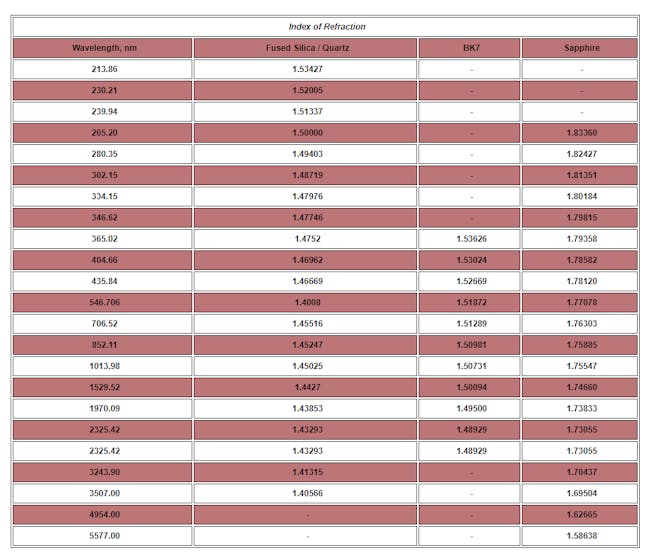
The sensor needs to be calibrated as the refractive index for the window changes concerning the material which is one of the reasons. I have used a BK7 glass window which is commonly available.

Refractive index of BK7
We need to perform two experiments for the sensor to get some meaningful readings. To monitor the presence of Algae in water, the spectral reflectivity must be calculated first. For calculating Reflectance on the scale from 0.0 to 1.0, minimum and maximum reflectance must be measured first.
Experiment 1 -Dark Readings:
To get dark readings, the sensor can be kept in a pitch-dark room and the measurements can be taken. An average of 10 to 15 readings will work for this experiment. There must be no light/ source for light nearby.
Experiment 2 -Max Readings:
The second experiment is to record the maximum reflectance the sensor can record from a light source. For this, the built-in LED in the spectral sensor can be used. If there is no built-in LED, a white LED can be used. The LED and sensor must be on the same plane. A front surface mirror, as shown in the below image is required to perform this experiment. This is the reason for using a front surface mirror.

1 / 2 • Front surface mirror.
These readings must be taken for all 11 channels of the spectral sensors. By using the below formula, the reflectance of any sample kept before the sensor can be calculated.
float reflectance=(value - min_reflectance_value)/(max_reflectance_value - min_reflectance_value);
Future Works
Up to this, only the reflectance of each channel can be calculated. Further, using only the 680nm channel data and calibrating the reflectance against the known value of algae content in water, a scale will be created to predict algae growth in the water bodies.