Esp32 Cam Testing in Local Server
by hariramanil810 in Circuits > Wireless
8 Views, 0 Favorites, 0 Comments
Esp32 Cam Testing in Local Server
.png)
If you have hard-time 3d printing stuff and other materials which i have provided in this project please refer the professionals for the help, JLCPCB is one of the best company from shenzhen china they provide, PCB manufacturing, PCBA and 3D printing services to people in need, they provide good quality products in all sectors
Please use the following link to register an account in JLCPCB
Pcb Manufacturing
----------
2 layers
4 layers
6 layers
PCBA Services
JLCPCB have 350k+ Components In-stock. You don’t have to worry about parts sourcing, this helps you to save time and hassle, also keeps your costs down.
Moreover, you can pre-order parts and hold the inventory at JLCPCB, giving you peace-of-mind that you won't run into any last minute part shortages. jlcpcb.com/RNA
3d printing
-------------------
SLA -- MJF --SLM -- FDM -- & SLS. easy order and fast shipping makes JLCPCB better companion among other manufactures try out JLCPCB 3D Printing servies
JLCPCB 3D Printing starts at $1 &Get $54 Coupons for new users
The ESP32-CAM is a very small camera module with the ESP32-S chip that costs approximately $10. Besides the OV2640 camera, and several GPIOs to connect peripherals, it also features a microSD card slot that can be useful to store images taken with the camera or to store files to serve to clients.
Introduction
.png)
Formatting MicroSD Card
The first thing we recommend doing is formatting your microSD card. You can use the Windows formatter tool or any other microSD formatter software.
1. Insert the microSD card in your computer. Go to My Computer and right click in the SD card. Select Format as shown in figure below.

2. A new window pops up. Select FAT32, press Start to initialize the formatting process and follow the onscreen instructions.

Note: according to the product specifications, the ESP32-CAM should only support 4 GB SD cards. However, we’ve tested with 16 GB SD card and it works well.
.png)
.png)
Revise parameters
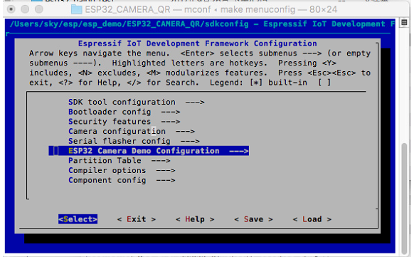
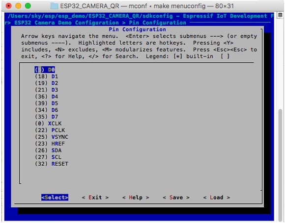
Input "make menuconfig", configure WIFI and Camera parameters.


4. Open file app_main.c, revise CAMERA_FRAME_SIZE, MERA_FRAME_SIZE(picture size) macro define(default configure JPEG)
5. Input "make flash monitor" onto terminal, compile the project and burn.

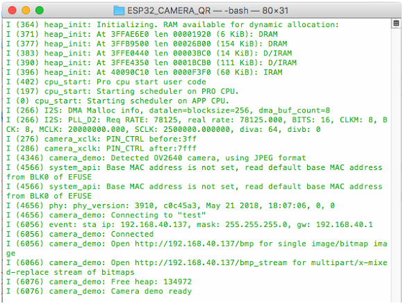
6. Check the serial port information or module IP information. Input http://module ip address+"/jpg to get the image, and please make sure that your computer and module are in the same LAN.
For example, the address the module got is 192.168.40.148.
The predecessor of ESP32, the ESP8266 has a builtin processor. However due to multitasking involved in updating the WiFi stack, most of the applications use a separate micro-controller for data processing, interfacing sensors and digital Input Output. With the ESP32 you may not want to use an additional micro-controller. ESP32 has Xtensa® Dual-Core 32-bit LX6 microprocessors, which runs up to 600 DMIPS. The ESP32 will run on breakout boards and modules from 160Mhz upto 240MHz . That is very good speed for anything that requires a microcontroller with connectivity options.
The two cores are named Protocol CPU (PRO_CPU) and Application CPU (APP_CPU). That basically means the PRO_CPU processor handles the WiFi, Bluetooth and other internal peripherals like SPI, I2C, ADC etc. The APP_CPU is left out for the application code. This differentiation is done in the Espressif Internet Development Framework (ESP-IDF). ESP-IDF is the official software development framework for the chip. Arduino and other implementations for the development will be based on ESP-IDF.
ESP-IDF uses freeRTOS for switching between the processors and data exchange between them. We have done numerous tutorials on freeRTOS and with all the bare-metal programming tutorials for ESP32 we will try and cover this aspect in detail. Although the feature set is great at the price at which the chip is being sold, the complexity is enormous.
Arduino Code
.png)
.png)
.png)
Once downloaded and installed open to the command prompt. Now we have to install a few libraries. For that run the following commands below one after another until all the libraries are installed.
pip install numpy
pip install opencv-python
pip install mediapipe
pip install playsound==1.2.2
Once you have entered these commands in the command prompt then these libraries will be installed. Now create a new folder.
import mediapipe as mp
import cv2
import numpy as np
import time
from playsound import playsound
cap = cv2.VideoCapture(0)
cPos = 0
startT = 0
endT = 0
userSum = 0
dur = 0
isAlive = 1
isInit = False
cStart, cEnd = 0,0
isCinit = False
tempSum = 0
winner = 0
inFrame = 0
inFramecheck = False
thresh = 180
def calc_sum(landmarkList):
tsum = 0
for i in range(11, 33):
tsum += (landmarkList[i].x * 480)
return tsum
def calc_dist(landmarkList):
return (landmarkList[28].y*640 - landmarkList[24].y*640)
def isVisible(landmarkList):
if (landmarkList[28].visibility > 0.7) and (landmarkList[24].visibility > 0.7):
return True
return False
mp_pose = mp.solutions.pose
pose = mp_pose.Pose()
drawing = mp.solutions.drawing_utils
im1 = cv2.imread('im1.jpg')
im2 = cv2.imread('im2.jpg')
currWindow = im1
while True:
_, frm = cap.read()
rgb = cv2.cvtColor(frm, cv2.COLOR_BGR2RGB)
res = pose.process(rgb)
frm = cv2.blur(frm, (5,5))
drawing.draw_landmarks(frm, res.pose_landmarks, mp_pose.POSE_CONNECTIONS)
if not(inFramecheck):
try:
if isVisible(res.pose_landmarks.landmark):
inFrame = 1
inFramecheck = True
else:
inFrame = 0
except:
print("You are not visible at all")
if inFrame == 1:
if not(isInit):
playsound('greenLight.mp3')
currWindow = im1
startT = time.time()
endT = startT
dur = np.random.randint(1, 5)
isInit = True
if (endT - startT) <= dur:
try:
m = calc_dist(res.pose_landmarks.landmark)
if m < thresh:
cPos += 1
print("current progress is : ", cPos)
except:
print("Not visible")
endT = time.time()
else:
if cPos >= 100:
print("WINNER")
winner = 1
else:
if not(isCinit):
isCinit = True
cStart = time.time()
cEnd = cStart
currWindow = im2
playsound('redLight.mp3')
userSum = calc_sum(res.pose_landmarks.landmark)
if (cEnd - cStart) <= 3:
tempSum = calc_sum(res.pose_landmarks.landmark)
cEnd = time.time()
if abs(tempSum - userSum) > 150:
print("DEAD ", abs(tempSum - userSum))
isAlive = 0
else:
isInit = False
isCinit = False
cv2.circle(currWindow, ((55 + 6*cPos),280), 15, (0,0,255), -1)
mainWin = np.concatenate((cv2.resize(frm, (800,400)), currWindow), axis=0)
cv2.imshow("Main Window", mainWin)
#cv2.imshow("window", frm)
#cv2.imshow("light", currWindow)
else:
cv2.putText(frm, "Please Make sure you are fully in frame", (20,200), cv2.FONT_HERSHEY_SIMPLEX, 0.8, (0,255,0), 4)
cv2.imshow("window", frm)
if cv2.waitKey(1) == 27 or isAlive == 0 or winner == 1:
cv2.destroyAllWindows()
cap.release()
break
Wiring
.png)
.png)
To detect the object the python code uses a step-by-step method of image or frame conversion. At first, it tries to convert the RGB image to Grayscale such that the difference in magnitude of color is greatly visible and mathematical operations can be performed easily. After that to blend in the colors, we blur the image, now the canny edge detection takes place where it easily detects the edges, thus now to properly join the edges detected we dilate the image. In the end, we retrieve the number of closed figures after detecting edges.
import cv2
import urllib.request
import numpy as np
url='http://192.168.1.61/'
##'''cam.bmp / cam-lo.jpg /cam-hi.jpg / cam.mjpeg '''
cv2.namedWindow("live transmission", cv2.WINDOW_AUTOSIZE)
while True:
img_resp=urllib.request.urlopen(url+'cam-lo.jpg')
imgnp=np.array(bytearray(img_resp.read()),dtype=np.uint8)
img=cv2.imdecode(imgnp,-1)
gray=cv2.cvtColor(img,cv2.COLOR_BGR2GRAY)
canny=cv2.Canny(cv2.GaussianBlur(gray,(11,11),0),30,150,3)
dilated=cv2.dilate(canny,(1,1),iterations=2)
(Cnt,_)=cv2.findContours(dilated.copy(),cv2.RETR_EXTERNAL,cv2.CHAIN_APPROX_NONE)
k=img
cv2.drawContours(k,cnt,-1,(0,255,0),2)
cv2.imshow("mit contour",canny)
cv2.imshow("live transmission",img)
key=cv2.waitKey(5)
if key==ord('q'):
break
elif key==ord('a'):
cow=len(cnt)
print(cow)
cv2.destroyAllWindows()
Setting Up
.png)
.png)
The NodeJS server sends the image to the Vision AI API. But to interact with the API it needs some authentication which is done using the Authentication ID. Once the frame is sent, the API returns the labels to the server, and from the server, these labels are sent to the ESP-CAM and from there, labels are displayed on TFT-Screen.
Arduino Libraries Installation
Now in order to the use TFT screen and read the data from the server we require a few libraries which can be installed using the Arduino library manager. To open Library manager press Ctrl+shift+I, it might take a few seconds to open according to the system specifications. Now in the search bar type the name of libraries and install them.
1. TFT_eSPI by Bodmer: https://github.com/Bodmer/TFT_eSPI
2. TJpg_Decoder by Bodmer: https://github.com/Bodmer/TJpg_Decoder
3. ArduinoJson by Benoit Blanchon: https://github.com/bblanchon/ArduinoJson
Now run the above code by writing “node test.js” in the command prompt (make sure you are in the right directory)
• You will see the labels printed in the log that is detected in the test.jpg image
Congratulations our major work is done, now we have to do the same using server as esp-cam
• Create a new folder with the name VisionServer, in that create another folder named resources and also a file named server.js
Data Collection From Cam
.png)
.png)
.png)
GCP and API Setup
The Google Vision API allows developers to easily integrate vision detection features within applications, including image labeling, face, and landmark detection, optical character recognition (OCR), and tagging of explicit content. We will be implementing the same Google Vision functionalities with the ESP32 Camera Module. We selected ESP32 CAM module because it is an ideal solution for image processing IoT applications.a
Before the whole setup makes sure you have added your credit/debit card in GCP, although the project won’t cost even a single penny. Still, because we are using GCP features they require a billing address.
At first, go to Google Cloud Platform(GCP) through the link here. And Create a new project.
- Here click on New Project
- Add a name to the project and organization can be kept as No Organization
Once the Billing is Enabled and Project is Created. Now we must enable the Vision API for your project. To do so go to this link here. And enable the API.
Now we have to create a service account for authentication. Go to this link.
- Select the project created
- Add a name to service account as well as ID(we don’t have to provide the full ID just a name, although the service ID is automatically generated)
- Now click on Create and Continue
- Click the Select a role field.
- Under Quick access, click Basic, then click Owner.
- Click on continue
- Now click on Done
Now we create a service account key:
- In the Cloud Console, click the email address for the service account that you created.
- Click Keys.
- Click Add key, then click Create new key.
- Click Create. A JSON key file is downloaded to your computer.
- Click Close.
Now open a Command prompt and run the command:
First, locate yourself to a directory where you wish to save the project and create a server. Now open the command prompt at that location.
• npm install –save @google-cloud/vision
• set GOOGLE_APPLICATION_CREDENTIALS=KEY_PATH
For example: set GOOGLE_APPLICATION_CREDENTIALS=”/home/user/Downloads/service-account-file.json”