Fully 3D Printed Toy Car With Planetary Gears
by Outware in Workshop > 3D Printing
434 Views, 3 Favorites, 0 Comments
Fully 3D Printed Toy Car With Planetary Gears

I created a 3D printed toy car showcasing planetary (epicyclic) gears. This Instructable will cover the process of designing, printing, and assembling a toy car.
Supplies


A 3D Printer to print body and wheels
PLA filament or whichever material you prefer
Super glue to glue all parts together
Lithium grease, PTFE lubricant, or silicone/dielectric grease to decrease friction in gears (Any other lubricant safe for PLA or your preferred material will work.)
Plastidip to increase grip on wheels (optional)
Masking tape (optional)
Onshape account or any CAD software
Gear Basics in Onshape
To design my project, I used Onshape, a free browser-based CAD website.
Create a new document > Navigate to the toolbar > Add custom features button on the right > FeatureScript samples > Spur gear - Custom Feature.
Using the spur gear feature in Onshape makes this project quite easy to design.
A few things to keep in mind:
- The module must remain constant to allow all gears to mesh together. Unequal modules will result in gears NOT meshing.
- Check the box labeled Helical then Double Helix, this will allow our gears to stay together without the use of a carrier.
- Selecting the Profile offsets dropdown and adjusting the backlash parameter will change the tolerance for 3D printed parts.
- Since we are using planetary/epicyclical gearing, we need to calculate the number of teeth for the ring (R), sun (S), and planet (P) gears. We can use the equation R=2*P+S or you can use this website to visualize and tinker.
For my design, I used gears with a 2.5mm module. The module parameter has a direct relationship with the size of the gear. A higher module will result in a larger gear and vice versa.
My gear design is comprised of:
- Five 9-tooth planet gears
- One 18-tooth sun gear
- One 36-tooth ring gear.
Creating the Ring Gear


Generating The Gear
To generate the gear, we will use the spur gear tool we added in the last step.
For my design, the parameters for my gear were:
- 36 teeth
- 45 mm depth
- 2.5 mm module
- 0.5 mm backlash
- Helical
- Clockwise
- 15 degrees
- Double Helix
A larger module and depth will result in a larger gear and overall size of car.
Now that you have adjusted the gear to your liking, click the green checkmark to save and exit the spur gear generator.
We are not finished, the gear has teeth on the outside, not the inside. This is not suitable for a ring gear.
Creating a Circle (Example One)
Now that we have a gear to our liking, we must create a cylinder to subtract the shape of gear from.
Using the view cube in the top right, select the front plane to view the project from the front. This should give you a flat view of the flat surface of the gear.
Use the sketch tool on the left in the toolbar to create a new sketch on the front plane.
Use the center point circle tool (c) to drag a circle from the center of the gear. It's okay for this to be an imprecise number.
Using the dimension tool (d), we can double click on the radius of the circle we just created and fine tune its size.
Click the green checkmark to save and exit the sketch once you are satisfied with the size of the circle in relation to the gear. The cylinder will be used as the wheel/tire, so keep that in mind.
Extruding a Cylinder (Example Two)
Once you have exited the sketch tool, click on the inner part of the circle and use the extrude tool (shift+e).
Confirm the extrude tool is marked as a new solid, not a surface. Adjust the depth size to match the depth of your gear.
Click the green checkmark to finalize the extrusion.
Using Boolean Tool to Create Ring Gear (Example Three)
Now that we have our cylinder and gear parts, we can use the boolean tool to subtract the gear from the cylinder, leaving us with a ring gear.
The boolean tool may not be visible in the toolbar by default, so feel free to use the search bar to find it.
Once you are in the boolean menu, select subtract.
Our tool is the gear and our target is the cylinder since we want to remove the shape of the gear from the cylinder.
Click the green checkmark to finalize the boolean.
Our ring gear is now finished!
You may want to rename the gear and hide it for now.
Creating the Planet and Sun Gears


This step uses the spur gear tool a few more times.
Remember: the module and depth must be the same for ALL gears.
We will begin with the planet gear, the least complicated.
Creating a Planet Gear
Just like the previous step, we will use the spur gear tool again.
All parameters will remain the same except for the number of teeth.
The planet gear is the smallest of the gears, orbiting around the sun gear within the ring gear.
My planet gear has 9 teeth.
I have 5 planet gears in my design, you can choose to have 3, 4 or 5.
Creating a Sun Gear
Once again, we will use the spur gear tool again.
The only parameters we are changing will be the teeth and switching the helical setting to counterclockwise.
The sun gear is the middle size of the gears, it is in the center with planet gears orbiting it.
My sun gear has 18 teeth.
Once you have finished generating the gear using the spur gear feature, we must also make a square hole in the center to hold the wheels onto the car body.
Creating a Square Hole
For this example, we will sketch a 20 mm square, but you can do whichever size fits your gear.
Use the sketch tool on the left in the toolbar to create a new sketch, selecting the flat face of the gear.
Use the center point rectangle tool (r) to drag a rectangle from the center of the gear.
Using the dimension tool (d), we can click on a side and adjust its size.
Click the green checkmark to save and exit the sketch tool.
Click on the inner part of the square so the entire square highlights orange, not one side. We will use the extrude tool (shift+e) again.
Confirm the extrude tool is marked as remove and not add. Adjust the depth to whatever size hole you'd like in you gear. I chose 25 mm.
Click the green checkmark to finalize the extrusion.
You should now have the Ring Gear, Sun Gear, and Planet Gear.
Designing the Car Body


Designing the car body is where you can really let your creativity flourish!
There must be adequate spacing between wheels and the car body. We don't want the wheels to rub against each other or the car body.
The wheel example has a radius of 110 mm, so we will sketch out a circle with a radius of 125 mm on the front plane.
In the last step, we created a 20 x 20 x 25 mm square hole in the gear.
To allow for some wiggle room, we will create a 19.5 mm square.
Now, create another 125 mm circle however far you'd like away from the other one.
For my example, I'll use 20 mm. Additionally, in my car, the distance between the centers of both circles is 145 mm.
If you have different dimensions, simply add the radius of the sketched circle and the distance between each circle to get this number.
Get creative with how you sketch out your car, make it your own!
Solidifying the Car
Now that we have a sketch of our car, we will once again use the extrude tool (shift+e).
Select all the faces you'd like to extrude. (Example shown).
Since our wheels are 45mm wide, we will extrude out 100 mm symmetrically.
Adjust this number depending on how far you'd like the body to protrude or how much you'd like the wheels to protrude.
Creating Wheel Wells
Now that we have the body of the car, we need to create wheel wells.
We will hide the car body and use the extrude tool again to remove material to create space for the wheels.
Adjust the starting offset depending on the size of the wheels and your design preferences.
Since our car body is 100 mm wide and our wheels are 45 mm wide each, I chose a 5 mm offset to bring it all together.
Repeat this on both sides.
Adjusting square pegs
The hole we created in our gear is 20 x 20 x 25. So we will adjust the peg to be around 30 mm. Select the square pegs and use the extrude tool to remove 15 mm.
Finishing touches
Now you can add fillets, chamfers, or other little details on the car and wheels.
Now you should be finished with the car body, and gears/wheels!
Slicing and Printing


I used my 3D printer, a Bambu Lab A1.
For the slicer, I used Bambu Studio.
Export your parts from Onshape by right-clicking on the parts and selecting export and STL format.
Import the parts into Bambu Studio or whichever slicer you prefer by dragging them from File Explorer into the workspace.
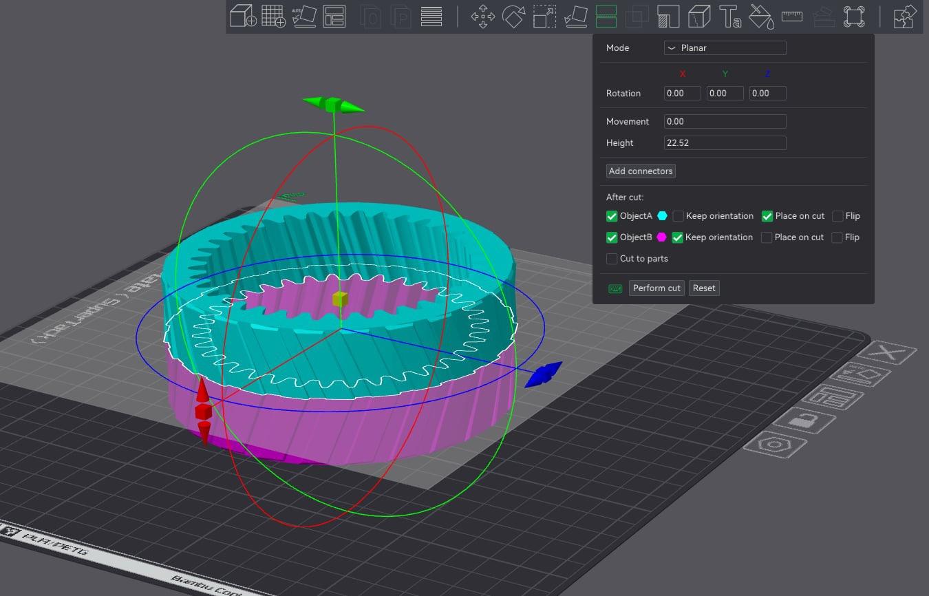
Start with importing the ring gear. In order to fit the sun and planet gears into the ring gear, we will have to cut it in half.
Cutting the Parts
Luckily, Bambu Studio has a feature called cut located in the top toolbar where you can split the part in half AND add connectors.
We will cut the gear in half as shown in Picture 1. In my case, Bambu Studio did not want to cut it straight in half so I adjusted the movement parameter to .10.
You can also add connectors to fit the two halves together. I'd recommend adding two connectors, each being a different shape. This will ensure the correct orientation for the halves when you assemble them. I have this shown in Picture 2.
Next, import the car body. It may not fit on the build plate depending on the size of your car, so we will have to cut it as well. Repeat the same steps of cutting and adding connectors. Connectors aren't as necessary for the car body, but it is nice to have the two halves interlock.
We will not have to cut the sun or planet gears.
Slicing and Printing the Parts
Changing print settings and slicer settings is quite extensive so I will not go in-depth on them here. You can find more information about slicing and printing on slicer wikis. Bambu Studio has its own wiki.
If your gears are quite small, enable brims to increase bed adhesion.
I recommend adaptive cubic or gyroid infill.
Some parts of your car body may require supports. Do not use supports on the gears.
Assembling the Car Body

We can now assemble the two halves of the car body!
If you did not need to cut your car in half, do not worry about this step.
If you used supports, the car body may have required some post-processing such as sanding.
My car is blue and white because I ran out of blue filament mid-print.
Apply super glue between the two halves.
Fun fact: Cyanoacrylate super glue pulls water from the air to polymerize/harden. You can lightly mist one half of the car body with water and apply super glue to the other to decrease drying times.
Assembling the Wheels


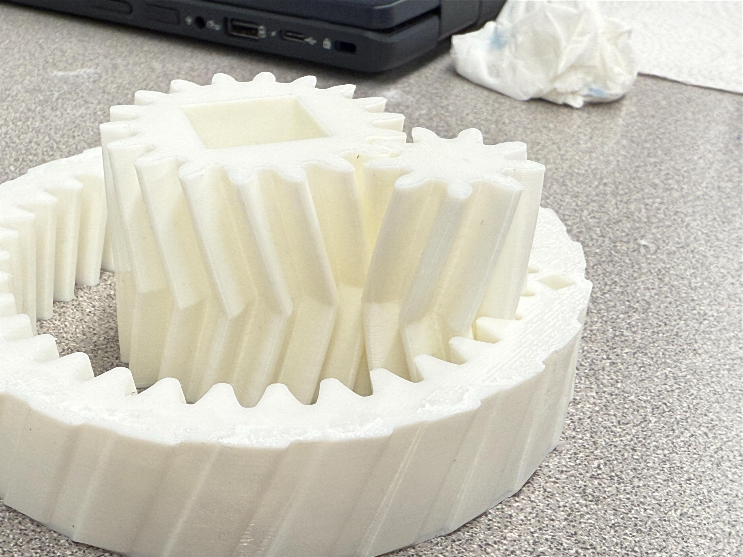
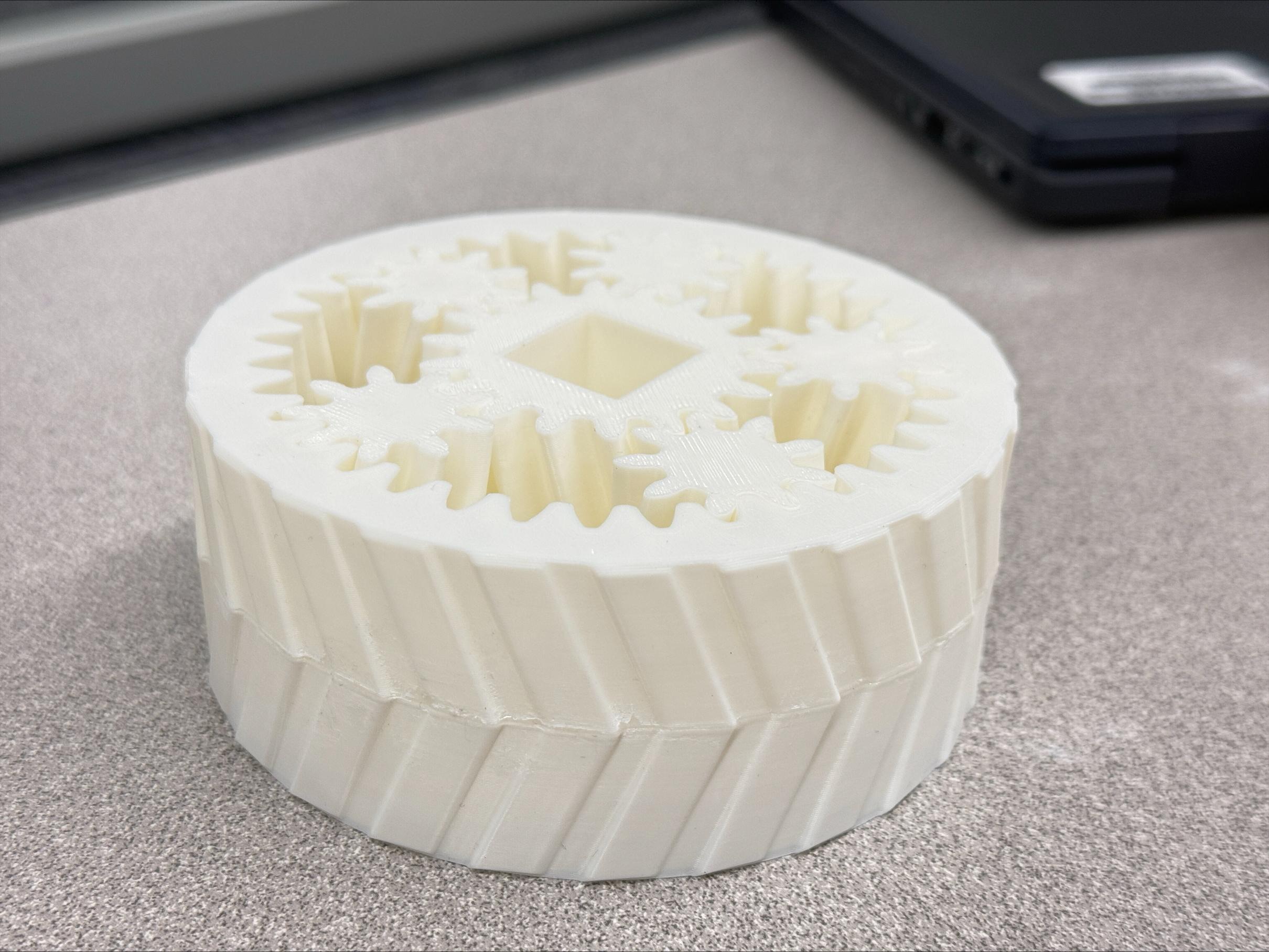
Attached above are the pictures of the assembly process.
- Lay down one side of the ring gear
- Put in the sun gear and one of the planet gears.
- Fit in more of the planet gears.
- The last planet gear will be a tight fit so you may have to push and maneuver the gear to seat it correctly.
- Get the top half of the ring gear and fit it onto the gear, lining up the connectors we made in the slicer.
- Using super glue, we will attach the halves together.
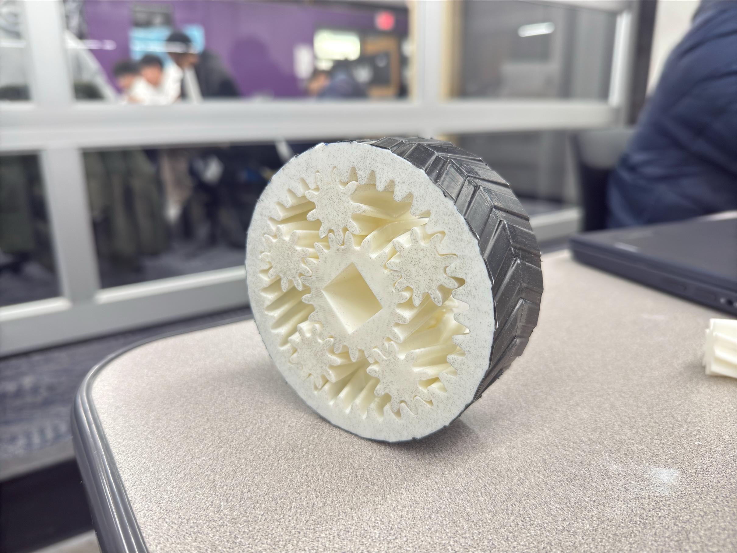
Now, you can choose to spray the gear with Plastidip for increased grip on smooth surfaces.
Use masking tape to cover the top and bottom of the gears.
Move to a well ventilated area to apply the coating and wait around 30 minutes between each coat.
After everything dries, consider using a lubricant for the gears. Some PLA safe lubricants:
- Lithium grease
- PTFE grease
- Silicone/dielectric grease
If you did not use PLA for this project, please research what lubricants or super glues are compatible with your chosen material.
Finishing the Car

To complete our car, we will use super glue or whichever attachment method you prefer. You can choose to put the glue on the peg or inside the hole in the sun gear.
I suggest painting your car or experimenting with a more interesting or exotic design.
Ultimately, this project is a chance to showcase your creativity and make much more interesting car designs than mine.