Making a Dollhouse Door With Zen Toolworks CNC
by zentoolworks in Workshop > CNC
3421 Views, 24 Favorites, 0 Comments
Making a Dollhouse Door With Zen Toolworks CNC

During the lifetime of a dollhouse, it is the doors that get the most use and are prone to getting damaged. But what are you going to do when the door finally breaks, you can’t glue it back together, and none of the doors you can find will fit properly?
You can simply make your own by milling one on a CNC machine!
Using this guide (and some materials/equipment listed below), you will be able to quickly and easily make your own replacement dollhouse door.
Equipment Used
- Zen Toolworks CNC machine with Mach3 controls
- 1/8 in diameter flat end mill
- 1 mm diameter ball end mill
Programs Used
- DeskProto 6.1
Materials Used
- MDF board
- double-sided adhesive
Designing Your Door

1. Open your model in Desk Proto and check the part dimension by clicking the yellow “I” on your toolbar. This will open up the Geometry Information window, where the x (width), y (height), and z (thickness) dimensions will be listed under the Delta column in millimeters.
If these dimensions are correct for your door, then you can start getting your G-codes set up. Most likely, however, you will need to adjust the values of the dimensions.

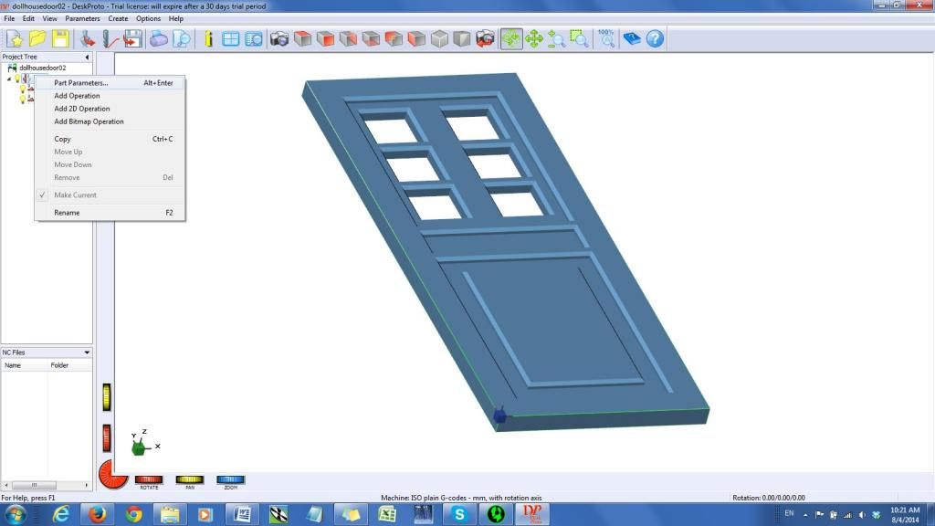
2. Go to the Part Parameters window, either by right-clicking your part in the Project Tree and selecting Part Parameters, or by selecting it in the Parameters menu above the toolbar.

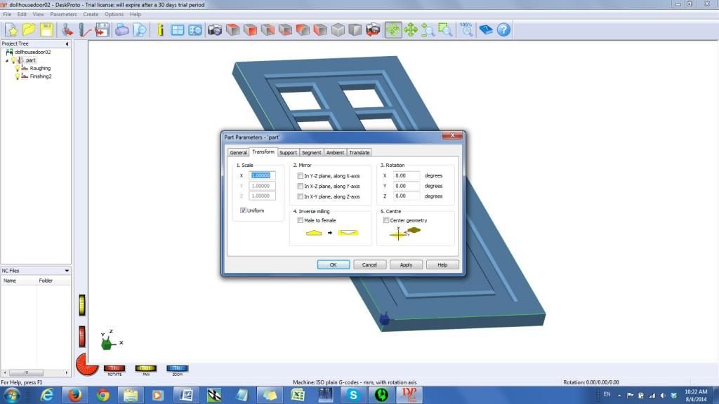
3. In the Transform tab, under 1. Scale, you can then adjust your dimensions. If the proportions for the model and your required door are the same, you can check Uniform. If each dimension needs to be adjusted separately, uncheck the Uniform box.
4. The numbers in the X, Y, and Z boxes are what you need to multiply the current value by to get to your desired value. Therefore, you will need to calculate the ratio of your desired value to the current value and put in that number. (input number = desired value/current value) IMPORTANT: Your Z-dimension (thickness) is critical. It needs to either be exactly the same as your actual board so that the windows and door itself can be cut out, or slightly smaller (but thin enough that you can cut out the door and windows with a knife). If you make the thicknesses the same, make sure that the door is securely attached to your work platform.
5. Check to make sure that your new dimensions are correct in Geometry Information.
Setting Up G-Code

In addition to making modifications to our 3D model, we can also use DeskProto to simulate our machine toolpaths and create the G-code used to run the machine.
6. Right-click your part in the Project Tree, and select Add Operation. Then, right-click the new operation and select Operation Parameters. In the Operation Parameters window, you can then input all the parameters for the roughing pass. The following bullets are the parameters we used, but you’re free to change them if you wish.
- Rename the operation to Roughing (or whatever you want, as long as you know what it’s for).
- Select your tool bit. We used a 1/8 in flat end mill for our roughing pass.
- Under Precision, select the distance between toolpaths and stepsize along the toolpath. The distance between toolpaths is how close each cut will be to the cut before it (or how deep the cut is). We selected d/9=.42 mm for both parameters.
- Input your desired feed rate. We ran ours at 300 mm/min. You can increase it if it cuts smoothly without chattering, or decrease it if your setup chatters.
- The spindle speed for our machine is manually controlled, so we left it at 2000 rpm. If your machine reads spindle speed from the code, calculate your appropriate spindle speed. (RPM = velocity for the material/circumference of the tool bit)
- Under the Strategy Tab, we left it at the default Parallel and Along X-axis.
- IMPORTANT: Under the Roughing Tab, we set the layer height at 0.40 mm, and skin thickness at 0.30 mm. If you increase the layer height much more, you run the risk of breaking your tool bit.
- The rest of the options were left at default.
7. Now, add another operation to your Project Tree for your finishing pass. Again, here are our parameters:
- Name: Finishing
- Tool: 1 mm diameter ball end mill
- Distance between toolpaths/stepsize along the toolpath: d/9=.11 mm
- Feed Rate: 300 mm/min
- Skin thickness: 0.0 mm
- Under the Advanced tab, under Ambient skipping, we selected Skip hor(izontal) ambient. This makes it so that time is not wasted traveling across previously cut space (ie. the windows)
- The rest of the options were left at default.
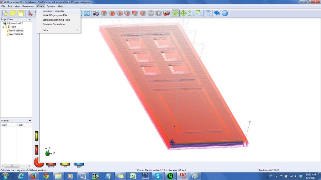
8. When all of your parameters have been correctly inputted, select Calculate Toolpaths under the Create menu at the top. This will create red lines over your model, simulating how the machine will cut your part. You can view the toolpaths for the separate operations by selecting/deselecting the yellow lightbulb icons by each operation name.
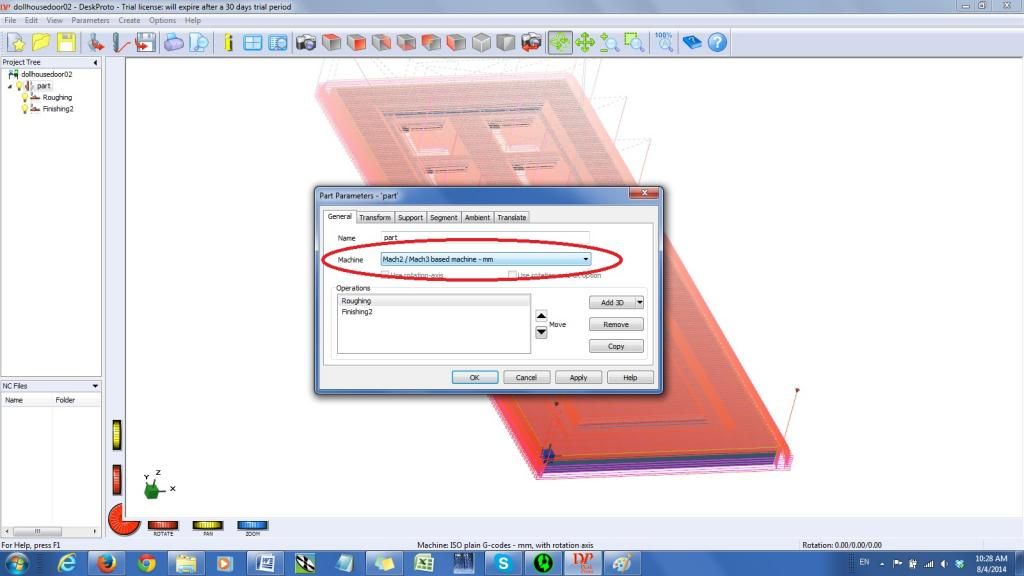
9. Before having DeskProto create the G-codes for each operation, check your Part Parameters and make sure that the correct machine has been selected. We will be using the Mach 2/Mach 3 based machine – mm.
10. Now, you can create and save your G-codes by selecting Write NC-program Files under the Create menu.
To the Machine!

12. Open up your Mach3 controls, and load your Roughing cut G-code. Before you can press GO, however, you will need to set up your machine origin. Remember how in the 3D model that the origin was at the bottom left hand corner of the part? Now, you’re going to have to place the tip of your tool at where you want that point. If you’re using a board that has been previously used, you will need to be careful about allowing enough room for your door.
13. After setting up your origin, you can simply start running your G-codes! Keep an eye on the setup at the beginning to make sure that everything is rigid and that your feeds, spindle speeds, and cut depths are adequate for your machine. If they aren’t, it’s much easier to go back to DeskProto and get those fixed at the beginning than waiting until you’re halfway through the cut, or your tool breaks. Also, make sure to not change your origin or move your workpiece before running your Finishing cut G-code. When you’re done, simply take your new door out and install it in your dollhouse!

