(Not So) Mini Lambda-Class Imperial Shuttle Popsicle Stick Model
by popsicle_mini-models in Workshop > Woodworking
22089 Views, 308 Favorites, 0 Comments
(Not So) Mini Lambda-Class Imperial Shuttle Popsicle Stick Model


**** SHUTTLE TYDIRIUM, what is your cargo and destination? ....>>>> *****
Hello everyone! Here's an instructable that pushes the size limits possible for a popsicle stick model - A Lambda-class Imperial Shuttle from the Star Wars Saga.
Manufactured by Seinar Fleet Systems for the Empire, the Lambda-class shuttle is the transport of choice for Imperial dignitaries including Emperor Palpatine and Darth Vader.
This mini popsicle stick project depicts the Imperial shuttle in two modes, in flight and landing modes.
The models were tedious to build because of the multiple , laminated layers required for the major parts. I can sum up this build in two words - LAMINATE and CARVE. The project took a lot of time to finish because of the numerous layers of parts that must be laminated using slow-curing White Elmers Glue as adhesive. The project was worth it though and I'm happy to share this instructables to everyone!
Materials and Tools


The models used a lot of regular-sized popsicle sticks, bamboo coffee stirrers and wooden ice cream spoons. Specifically, thirteen (13) layers of regular-sized popsicle sticks made up the upper fuselage of the shuttle. Twenty-three (23) layers of bamboo coffee stirrers made up the lower fuselage and fifteen (15) layers of wooden ice cream cup spoons made up the cockpit/command center. The large tongue depressor-sized sticks makes up the huge dorsal, port and starboard stabilizers (aka wings!).
Excess wood parts from my spares box produced the models' port and starboard intake coolers, main drive unit, and dorsal air intake. Various other small parts that produced the landing gear details and armaments likewise came from my spares box.
Tools used for the build were as follows:
- Dremel 3000 & Dremel Minimite with the following attachments:
- Coarse and Fine Drum sander
- Fine disc Sander
- #193, #199, #121 & #125 High speed cutter
- Standard & reinforced cut-off wheel
- #83702, #84922 & #85622 Silicone Carbide grinding stones
- #541, #932 Aluminum Oxide grinding wheel
- Olfa cutter
- Fine tweezers
- Mechanical pencil
- Ruler
- Various Clamps
- Elmers White Glue
- Cutting mat
Particularly helpful for this build were Dremel's workstation and flex tool shaft and a set of "third hand" from Thinkgeek.com.
Schematics and Images


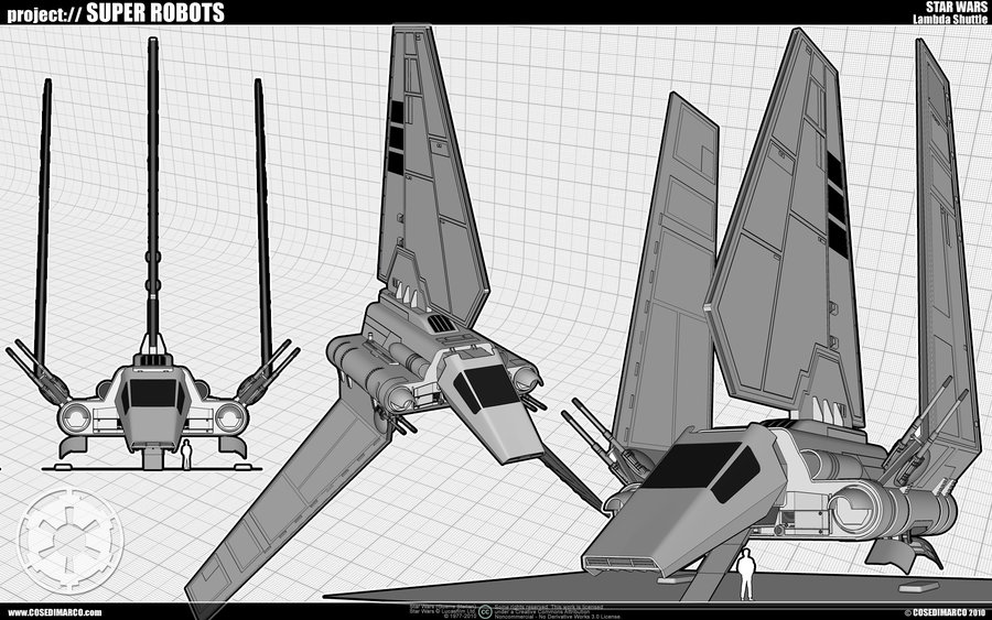

The keywords I used for both Bing and Google images search were "lambda shuttle".
The main schematics I used were from theforce.net. The site provided two blueprints depicting the shuttle in both landing and flight mode. This instructable will describe details in producing either of the two versions.
Other images provided visual reference for the shuttle's other details such as the landing gear assemblies and armaments.
I'd like to acknowledge the generous providers who posted the following useful reference for the project:
http://www.theforce.net/swtc/Pix/blue/shuttle2.jpg...
http://www.theforce.net/swtc/Pix/blue/shuttle3.jp...
http://www.theforce.net/swtc/Pix/blue/shuttle2.jpg...
http://fc02.deviantart.net/fs70/i/2010/238/6/8/La...
http://www.theforce.net/swtc/Pix/blue/shuttle2.jpg...
http://img4.wikia.nocookie.net/__cb20080501163334...
http://img2.wikia.nocookie.net/__cb20110426162810/...
The plans I used can be downloaded from this article. I've also included the schematics from my previous X-wing project in order to get the appropriate scale for the lambda shuttle.
The scaled shuttle makes this build the biggest starship/starfighter I ever came up with using popsicle sticks and similar materials.
Downloads
Cockpit Command Center




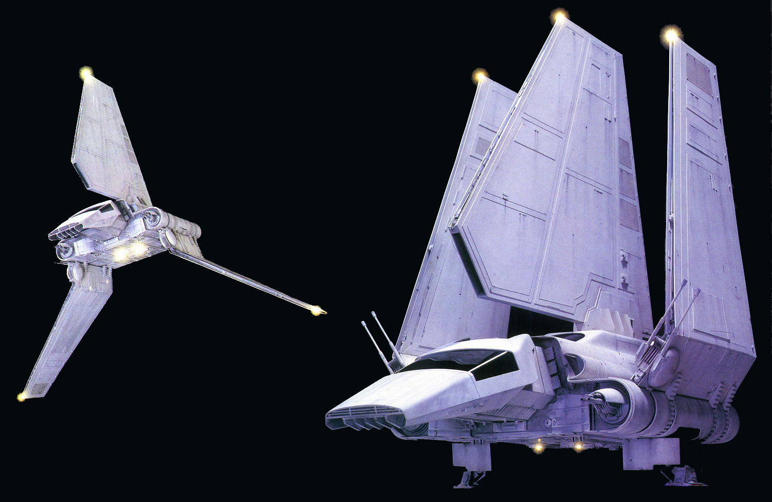
The main difference between the shuttle in landing and flight modes were the depiction of the boarding ramp, landing gear details, retracted wing and wing blasters (in landing mode). The flight mode has the port and starboard stabilizers (wings) and wing blasters deployed. Both the boarding ramp and landing gear were retracted in flight mode.
Cockpit command center (flight mode)
The cockpit command center was made from fifteen (15) layers of wooden ice cream spoons comprising three sections: 1) Center section containing the retracted boarding ramp consists of five (5) pieces; 2) Middle section with six (6) pieces (three per side); and the 3) Outer section consisting of four (4) pieces (two per side)
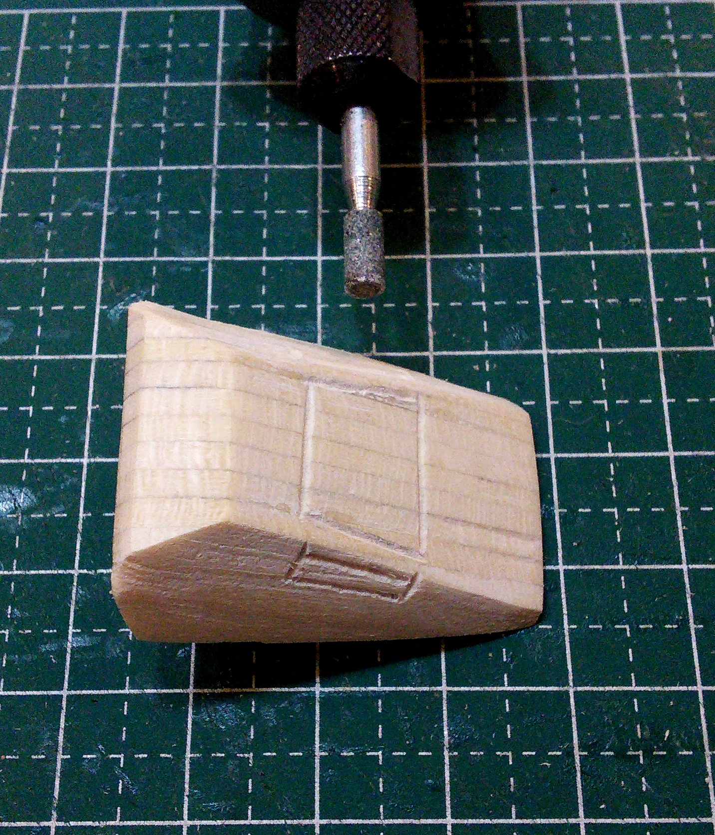
The shape of the cockpit was patterned from theforce.net schematics. Only the Center section retained the shape of the schematic since the middle and outer sections required trimming to get the desired contour as shown in supporting images.
The center section was laminated first using white glue as adhesive. The three pieces of middle layer were added on each side of the center section and allowed to dry thoroughly. The final two pieces comprising the outer layer were glued to each side of the middle layer to complete the solid blocked-shape cockpit.
The blocked-shaped cockpit was sanded with a coarse/medium drum sander attachment on a Dremel 3000 moto tool to get the sloping shape of the shuttle's command center. The shape was finished with a fine disc sander attachment on a moto tool. An outline was drawn on the cockpit for the front and side windshield. The outline was then etched permanently using a #83702 silicone carbide grinding stone attachment. The etched windshields gave the otherwise flat and featureless cockpit command center some details. This was my first project at etching popsicle sticks to bring out some of the details and it was worth the effort. It did require steady hands on a flexible dremel shaft to ensure straight and consistent lines for the windshield details.
To model the communications array below the cockpit, spare popsicle sticks were cut into six (6) tiny triangles and glued into place.
Cockpit command center (Landing mode)
The steps in fabricating the cockpit command center in landing mode was similar to the steps in making the cockpit in flight mode except for the trimmed center section to simulate the boarding ramp access. Three pieces from the center section's five pieces were cut to create the boarding ramp access. After the three pieces were laminated together using white glue, the assembly was enclosed with the remaining two layers to complete the center section of the cockpit command center.
As with the steps in making a cockpit command center in flight mode, the three pieces of middle layer were added on each side of the center section and allowed to dry thoroughly. The final two pieces comprising the outer layer were glued to each side of the middle layer to complete the solid blocked-shape cockpit.
The blocked-shaped cockpit in landing mode was similarly sanded using a coarse/medium drum sander attachment on a Dremel 3000 moto tool to get the sloping shape of the shuttle's command center. The shape was finished with a fine disc sander attachment on a moto tool. An outline was drawn on the cockpit for the front and side windshield. The outline was then etched permanently using a #83702 silicone carbide grinding stone attachment. The etched windshields gave the otherwise flat and featureless cockpit command center some details.
To model the communications array below the cockpit, spare popsicle sticks were cut into six (6) tiny triangles and glued into place.
The boarding ramp was made from a spare popsicle stick from the spares box, cut and carved into shape using a medium grit drum sander attachment and finished with a fine disc sander attachment on a moto tool. The boarding ramp must fit into the gap made in the cockpit's center section.
Upper and Lower Fuselage Assemblies


The upper fuselage contains the Lambda-class shuttle's passenger and cargo module. The upper fuselage of the popsicle stick model was made from thirteen (13) regular-sized popsicle sticks laminated with white glue and carved into shape using coarse/medium grit drum sander attachment and finished with a fine disc sander attachment on a moto tool.
Since the upper fuselage also houses the rear laser cannon mount, the upper fuselage's rear end was beveled using a coarse/medium grit drum sander attachment and finished with a fine disc sander attachment on a moto tool. A cavity was carved out using a 1/4" coarse grit drum sander attachment, #541 aluminum oxide grinding wheel and finished with a #83702 silicone carbide grinding stone attachment on a moto tool. A cavity was carved out using a standard cut-off wheel attachment. The cavity allows for the alignment of the dorsal air intake assembly with the upper fuselage during final assembly.
To make the port and starboard air intake that will be mounted on the sides of the upper fuselage, four (4) spare bamboo coffee stirrers were used (two per air intake). After each set was laminated with white glue and allowed to dry overnight, a notch was initially made using a cutting wheel attachment on a moto tool. The notch was made larger and rounder with a #84922 silicone carbide grinding stone attachment and finished with a fine disc sander attachment on a moto tool. The rear end was also tapered using a fine disc sander attachment.
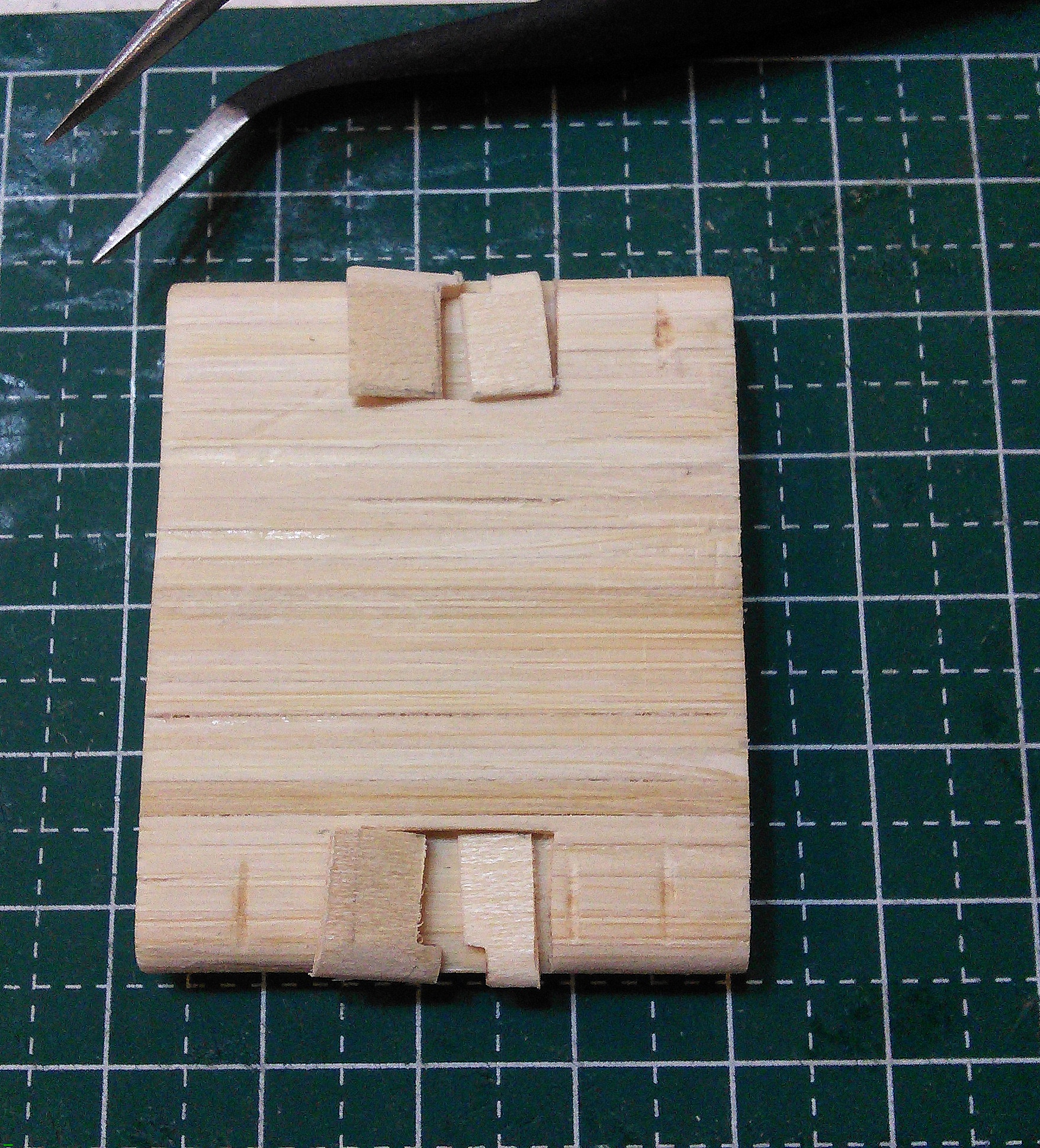
The shuttle's lower fuselage houses the landing gear assembly (for landing mode) and mounts the main drive assembly to the rear. The lower fuselage was made from twenty-three (23) layers of bamboo coffee stirrers laminated with white glue. Gluing the twenty-three (23) layers together posed a unique challenge to the project. I glued sets of three (3) layers at a time and made sure the bond is seamless by using various plastic clamps. Layer by layer, I built up two halves of the lower fuselage using the previous technique of gluing and clamping. Finally, gluing the two large pieces together required the use of a large plastic c-clamp to ensure a seamless fit. After allowing the clamped assembly to dry overnight, the lower fuselage was sanded using a coarse/medium grit 1/2" drum sander attachment and finished with a fine disc attachment on a moto tool. The edges were rounded off using a medium grit 1/2" drum sander attachment on a moto tool.
The main drive units were made from two (2) layers of spare tongue depressor-sized popsicle sticks. Two slots were carved for each layer using a standard cut-off wheel on a moto tool. The slots were made bigger with a #199 high speed cutter attachment. The slots were finished with a fine disc sander attachment on a moto tool. The two layer were laminated and allowed to dry overnight. The edges were rounded off and finished with a fine disc sander attachment.
Dorsal Air Intake

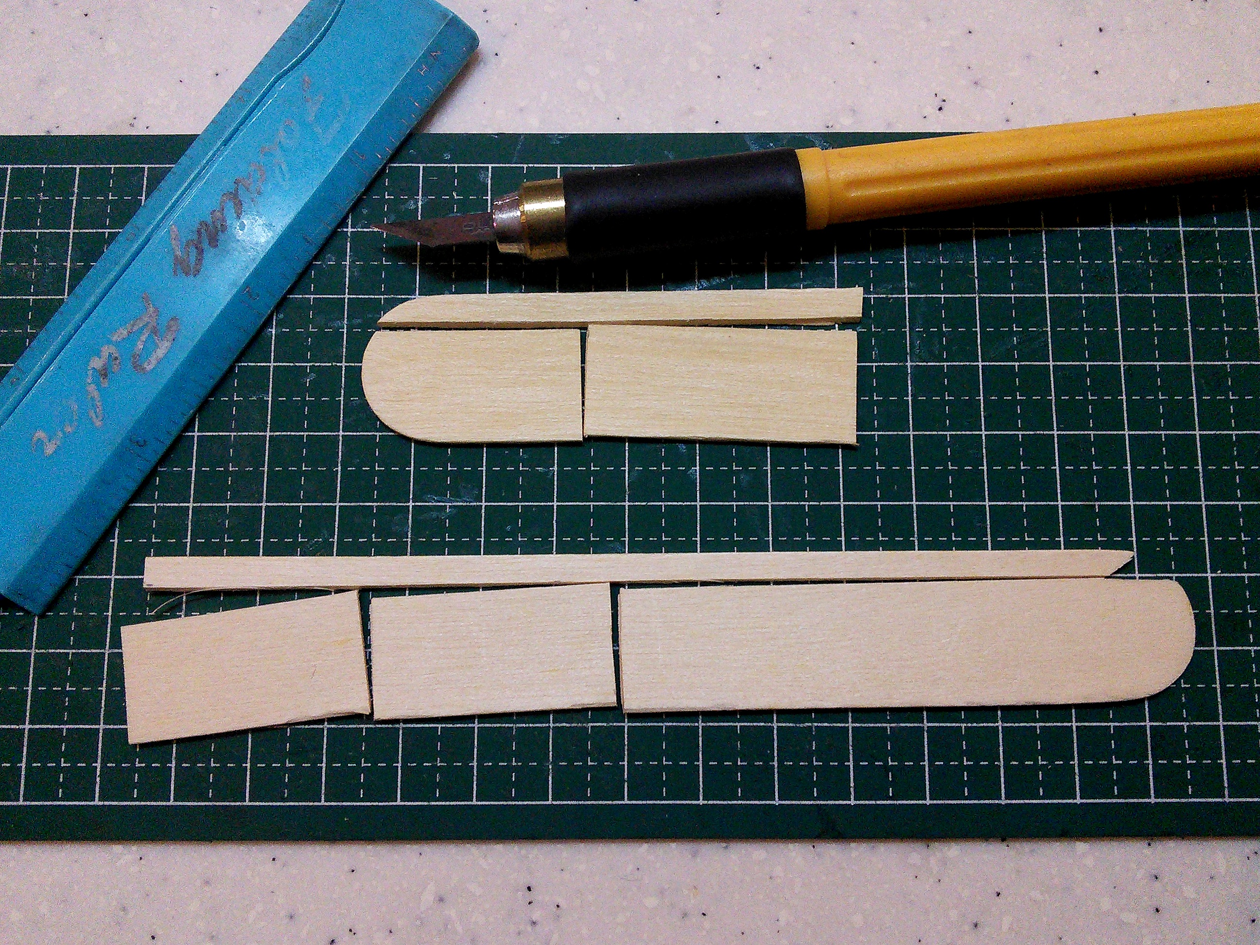


The dorsal air intake sits on top of the upper fuselage and mounts the shuttle's huge dorsal stabilizers. The air intake was made from three (3) layers of spare tongue depressor-sized popsicle sticks. A gap was carved from the two (2) lower halves using a standard cut-off wheel attachment. The two layers were laminated and held together with plastic clamps. The gap in the lower layers holds the three (3) slats that directs airflow into the air intake.
The top layer covers the gap and the three slats. It was shaped with a slight bulge to the rear that shall line up with the dorsal stabilizer later in the build.
The three (3) slats were from scrap thin coffee stirrers cut and shaped with a fine disc sander. I glued each slat in the gap made by the two lower layers, making sure that the slats are straight and even.
I used a medium grit 1/4" drum sander attachment to carve a cavity at the rear of the dorsal air intake. The cavity should line up with the cavity initially made at the rear end of the upper fuselage during final assembly.
Dorsal, Port and Starboard Stabilizers




Probably the most interesting sub-assemblies of the Lambda shuttle were the dorsal, port and starboard stabilizers (aka wings). These parts distinguish the shuttle from my other projects due to the rather huge pieces required to build them. I decided previously to etch some details since the assembled pieces would seem huge, dull and flat without it. Again, it did require steady hands on a flexible Dremel shaft to ensure straight and consistent lines for the wing details.
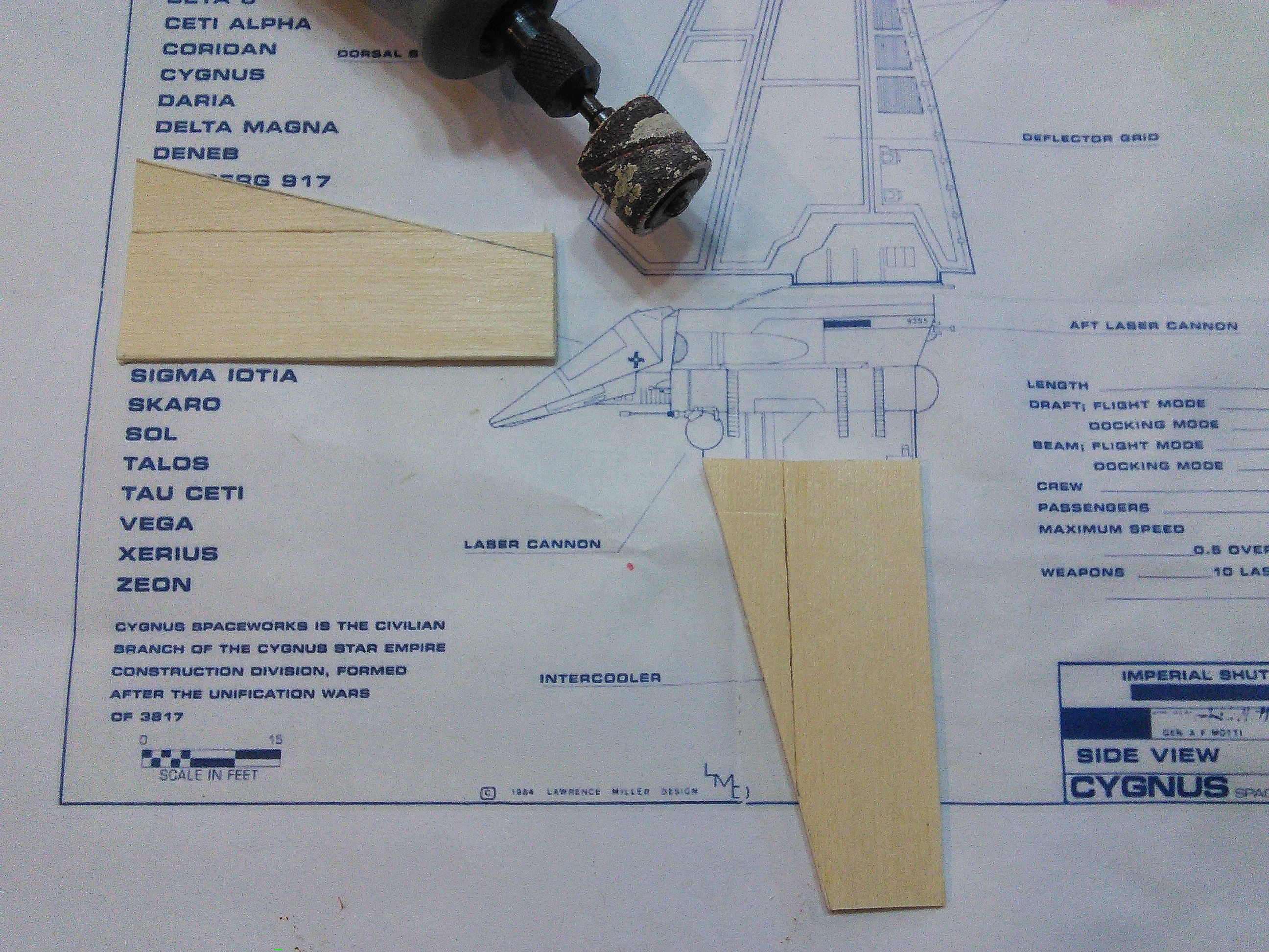
For the huge dorsal wings, no less than three (3) wide tongue depressor-sized popsicle sticks were needed. Each large piece was cut with an Olfa cutter using the schematics from theforce.net as major reference. I etched lines across each part with a #932 aluminum oxide attachment before I glued each huge part together. Even with the wide tongue depressor-sized popsicle sticks, I still added a scrap triangle to fill the gap between the middle and trailing wings. After the assembly has dried, I etched other details using a #83702 Dremel attachment. I finished the dorsal wings with a fine disc sander attachment, making sure that the edges were straight and even.
Scraps from the dorsal wings were used for the wing mount. The wing mount was made from three layers with the thin middle layer creating a gap that should fit the dorsal wing when dry.
The port and starboard stabilizers were made from the same wide tongue depressor-sized popsicle sticks. The port and starboard 'wings' required one and a half tongue depressor-sized popsicle sticks. The 'half' needed to be diagonally sliced with an Olfa cutter before it can be glued to the bigger half. The excess edge of each wing was carved off using a medium grit 1/2" drum sander attachment.
Using the schematics for reference, I traced the details on each wing and etched each side using a #932 aluminum oxide grinding stone attachment. The reverse gull wing for each wing was from a scrap tongue depressor-sized popsicle stick. I made sure that each reverse gull wing was glued in the correct angle as shown in various illustrations.
Blasters and Laser Cannons


With the completed wings, fuselage and canopy, now comes fabrication of some tiny parts - Blasters and laser cannons.
I started with fabricating the gun shields for the forward firing laser cannons. These parts were to be mounted at the front edge of the lower fuselage in the final assembly. The gun shields were made from scrap wooden dowels, drilled at one end using a #125, #121 High speed cutter and #83702 Dremel attachment. The round 'shield' was then cut off one edge using a standard cut-off wheel attachment on a moto tool. It was then cut in half using an Olfa cutter for each side of the lower fuselage.
The blasters and laser cannons were made from toothpicks shaped with a #541 aluminum oxide grinding wheel attachment on a moto tool. The laser cannons were mode thinly shaped than the blasters with the bases cut leaving only the barrels and flash suppressors. I needed six laser cannons (four forward firing and two rear mounted) and four blasters for the shuttle. Suffice to say that the craft was well armed for a transport/cargo vessel.
The rotating blaster mounts were also made from spare wooden dowels rounded at the end with a fine disc attachment and detached with a standard cut-off wheel attachment on a moto tool. I needed to make five (5) gun mounts (four for the wings and one for the rear-facing laser cannons) for the lambda-class shuttle.
Completing the Build







Shuttle in flight mode
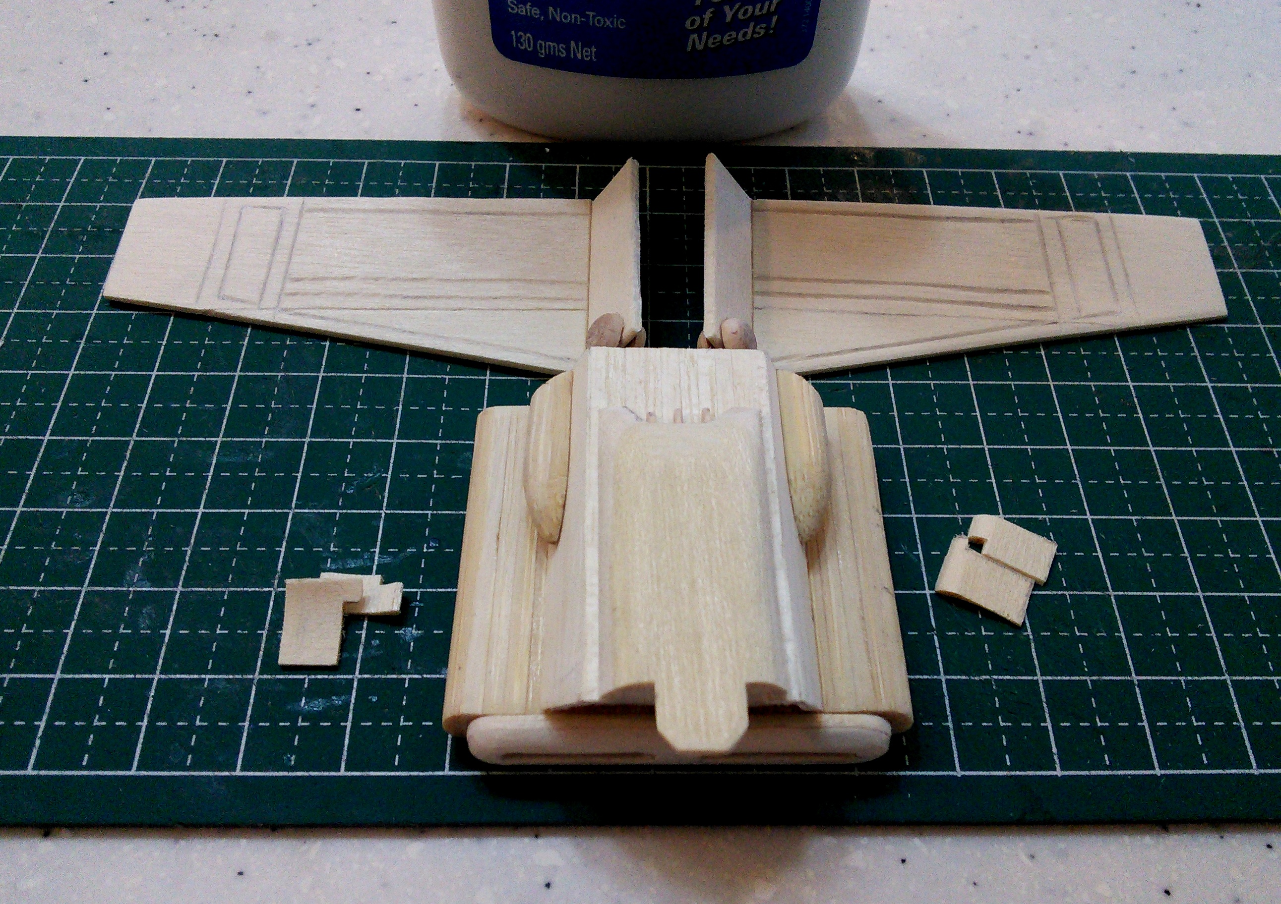
The lower fuselage assembly was first glued to the upper fuselage assembly. Next, the dorsal air intake assembly was glued on top of the upper fuselage making sure the cavity made in each sub-assembly lines up. When the glue has dried, the port and starboard air intakes were glued at opposite sides of the upper fuselage next.
Going to the rear of the fuselage, the main drive unit was glued to the lower fuselage next. The gun mount for the rear facing laser cannons were glued at the cavity where the dorsal air intake meets the upper fuselage. A slot was made using a standard cut-off wheel for the laser cannon mount. When the entire fuselage assembly was completely dry, I drilled tiny guide holes for the forward-facing laser cannons at opposite edges of the lower front fuselage using a #125 high speed cutter attachment.
The cockpit command center was glued to the completed fuselage assembly next. While the glue between the cockpit and the fuselage dries, I turned my attention to the port and starboard 'wings'. I glued the round blaster mounts at the front end of both sides of the inverted gull-wing in each of the port and starboard stabilizers.
Now comes the fun part.... I glued the four (4) tiny, forward-facing laser cannons on opposite ends of the lower fuselage. The tiny guide holes made the installation easier since the tiny laser cannons proved difficult to handle even with the use of tweezers. Next comes the gun shields that were glued on top of the forward-facing laser cannons. While waiting for the gun shields to dry, I glued the blasters in deployed position to each blaster mount on the inverted gull wings. Thinkgeek's third-hand was useful in suspending the wings in place while the bond between the blasters and the gun mounts harden. At this stage, I glued the huge dorsal stabilizer assembly on top of the dorsal air intake, making sure that the wings were straight and aligned.
Finally, the completed wings meet the completed fuselage/canopy assembly - one at a time. I must say that the shuttle in flight mode was truly majestic and fit for an evil emperor! And hey, didn't I see one flying over Frankfurt Airport a while back!?!
Shuttle in landing mode
Unlike the shuttle in flight mode, some other tiny parts were needed for the landing gear details.
I started with carving a space underneath opposite sides of the lower fuselage for the landing gear assemblies. A standard cut-off wheel attachment was initially used to make a guide slot for the landing gear cavity. A medium grit 1/4" drum assembly attachment was used to carve out the landing gear cavity and a #193 high-speed cutter was used to finish it.
Spare wooden ice cream spoons were used to fabricate the landing gear covers. It was initially cut with an Olfa cutter, carved out with a medium grit 1/4" drum assembly attachment and finished with a fine disc attachment on a moto tool. I used a standard cut-off wheel to make the intricate cut for each half of the landing gear cover.
The landing gear 'pads' were made from thin coffee stirrers cut to size with an Olfa cutter. The base were from a thicker popsicle stick scrap from my spares box. The long landing gear suspensions were fabricated from thinner wooden dowels also from my spares box. The suspensions were shaped using a fine disc attachment on a moto tool. Each set was carefully assembled making sure that the placement of the mounts and suspension on the landing gear pads conforms with downloaded illustrations and images.
The suspension 'guides' were a little trickier to make. They were made from 'solid' popsicle sticks carved into shape using a medium grit 1/2" drum sander and fine disc attachment on a moto tool.
With all the suspension parts fabricated, the assembly for the fuselage, canopy, dorsal stabilizer and blaster mounts in the port and starboard 'wings' were similar to the assembly made in the flight mode version. With these in place, I glued the blasters in a retracted position on the port and starboard wings. When these have dried, I glued the port and starboard wings to the fuselage/canopy assembly also in the retracted position.
Next, the landing gears and suspension supports were glued to the bottom of the lower fuselage. I needed to fabricate special mounts to prop up the shuttle while the landing gear assemblies bond with the fuselage. At this stage I glued the landing gear doors at the front and trailing edge of the landing gear cavities. Finally, I glued the boarding ramp at the bottom rear cavity of the cockpit command center. The boarding ramp serves as the 'stabilizer' that keeps the shuttle from tipping over at the front end.
Voila! Darth Vader's ride ready for take-off!