PCB Design Using EAGLE CAD

Introduction:
The objective of this project is to show how to design and create Arduino shields for many different applications using CadSoft's EAGLE software. We can then either ship off the designs to a company to mill them out or upload the designs using PCB-Gcode into our table top CNC machine and have it milled right before our eyes!
- Special Thanks to Boris Landoni at Open-Electronics.org, he was the original writer of the tutorial, we had just made it a bit more in-depth, the original can be found here:
http://www.open-electronics.org/how-to-make-an-arduino-shield-with-eagle-cad-tutorial/
Materials List:
- EAGLE CAD
- PCB-Gcode
Getting Software
- First we need to get the software necessary for this project:
- EAGLE can be attained at: http://www.cadsoftusa.com/download-eagle/?languag...

- PCB-Gcode can be attained at: http://www.cadsoftusa.com/download-eagle/?languag...
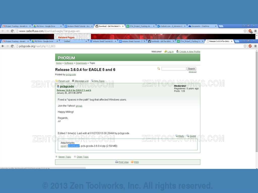
- EAGLE has a free trial version that allows only up to two layers. PCB-Gcode is completely free. After downloading both programs you will want to first install EAGLE CAD.
Planning Phase and Setup
- Open up EAGLE CAD. You should get a screen much like this one
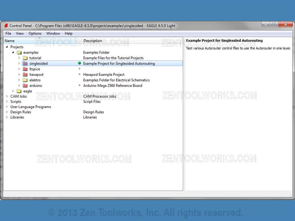
- For this example we are going to make an Arduino shield using 4 LED lights and 4 Switches. This circuit is for practice more than for application. This is to strictly demonstrate how to use EAGLE CAD for a working circuit.
- Go to File > New> Schematic.
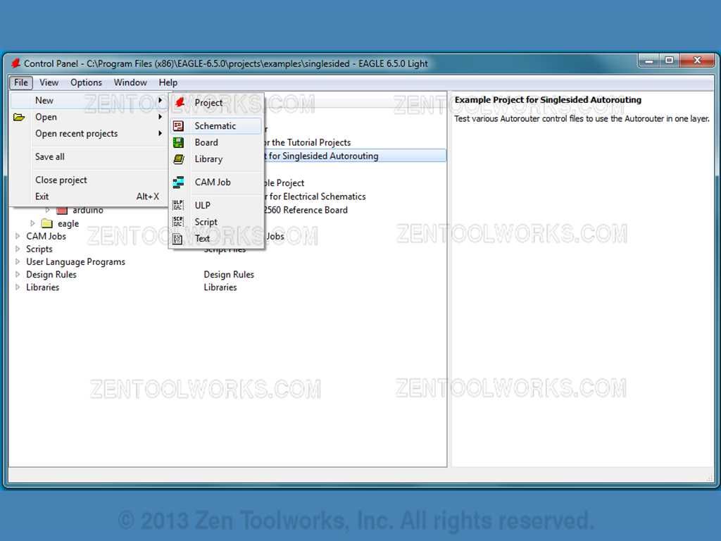
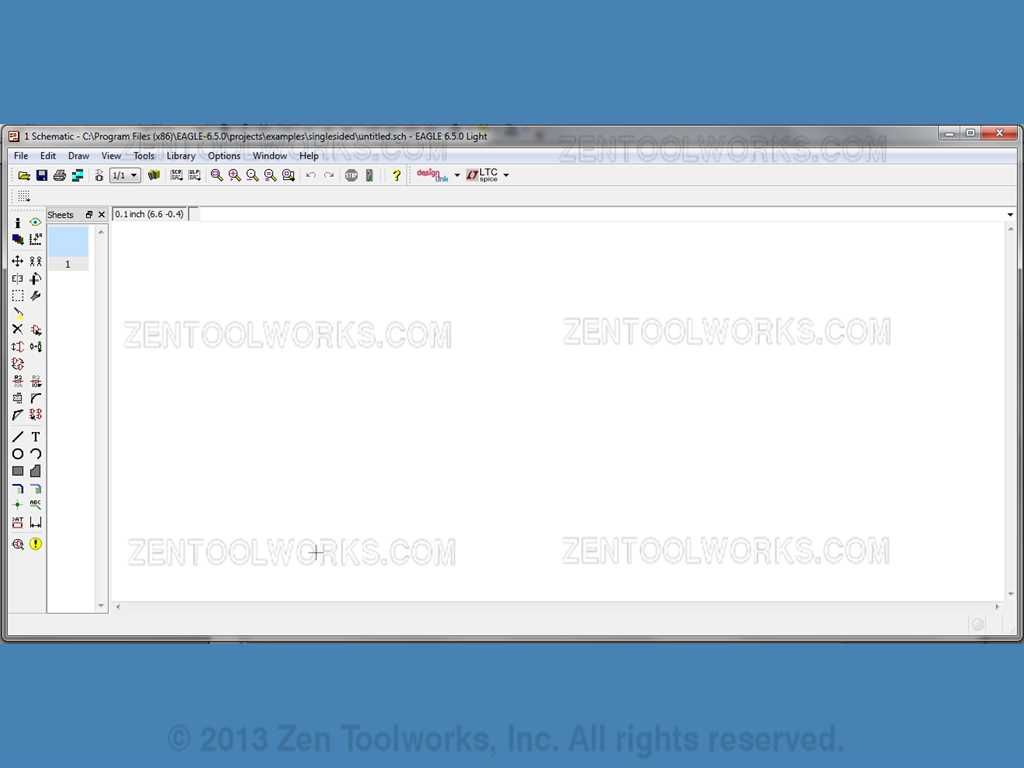
- It will take you to this screen:
Library Setup
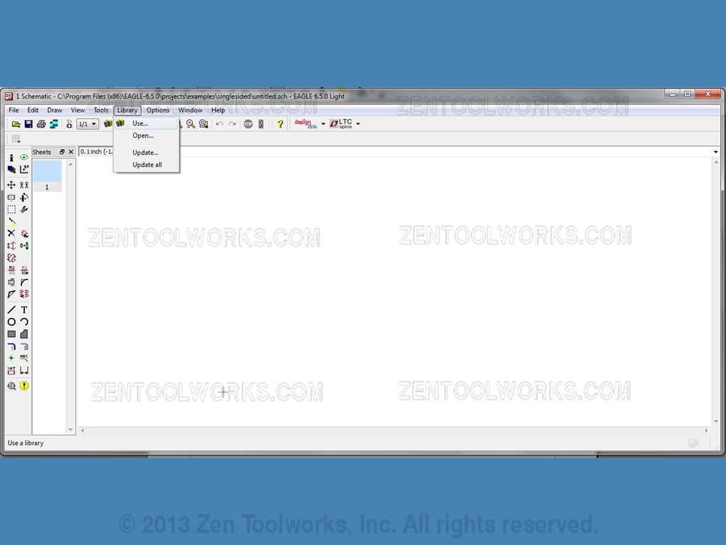
- Before we start building our schematic we have to add the libraries that we are going to use. We do this by going to Library>Use...
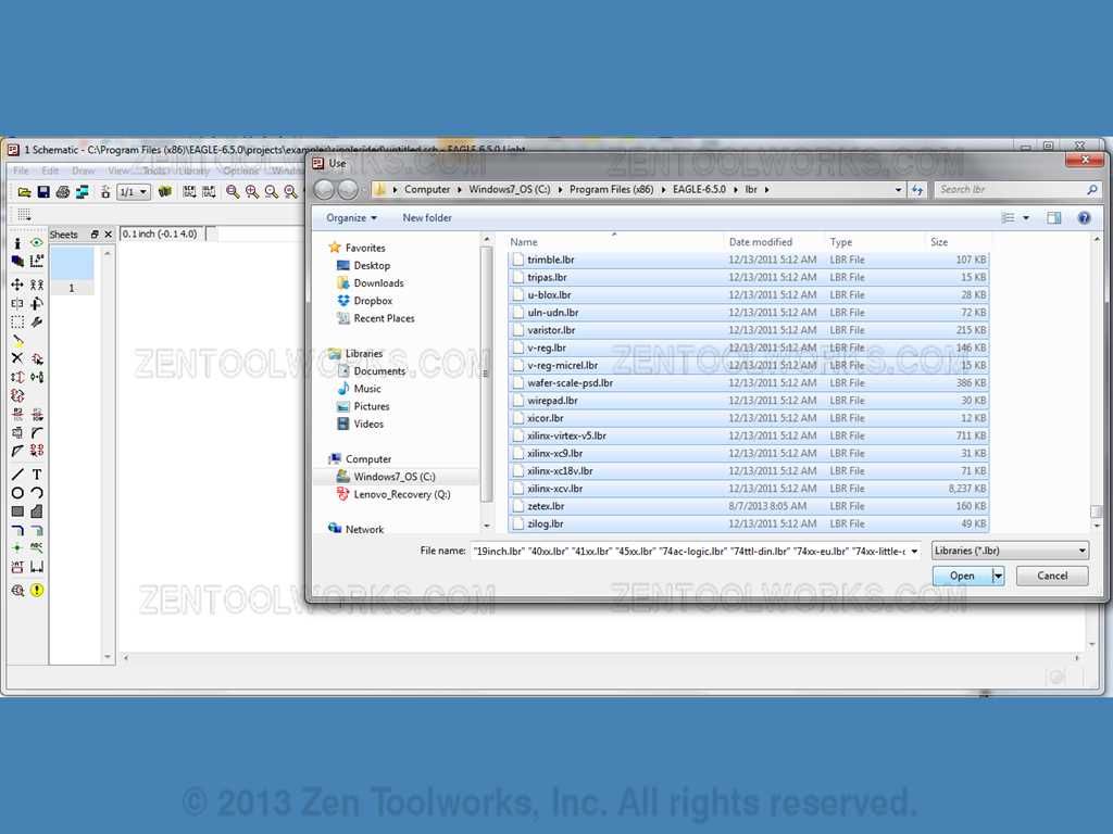
- We then highlight everything and press Open.
Part Placement Part 1: Placing Resistors
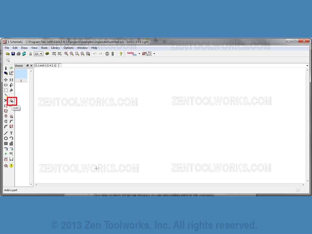
- Now that we have set up our libraries we can start adding parts to our schematic. We do this by pressing the symbol that looks like an AND gate.
- This will take you to the ADD screen.
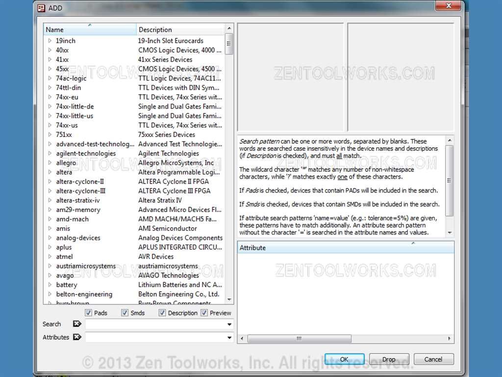
- We want to add some resistors. We do this by going to resistor>RE_U>RE_U_0207/10.
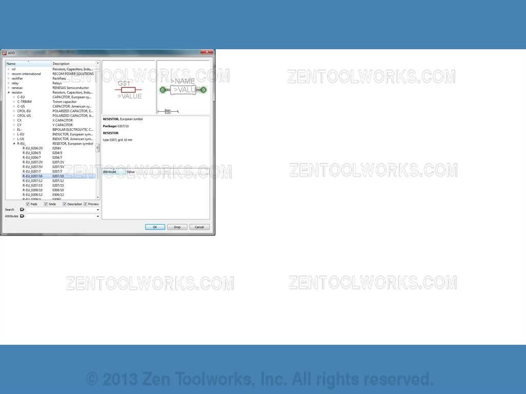
- Once we click OK we get our Plus cursor with the outline of our part.
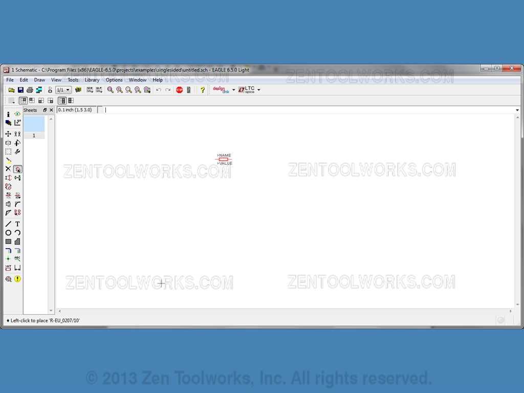
- We want to go ahead and place four resistors down. You do this by clicking, each click places a copy of the part we selected, in this case our simple resistor.
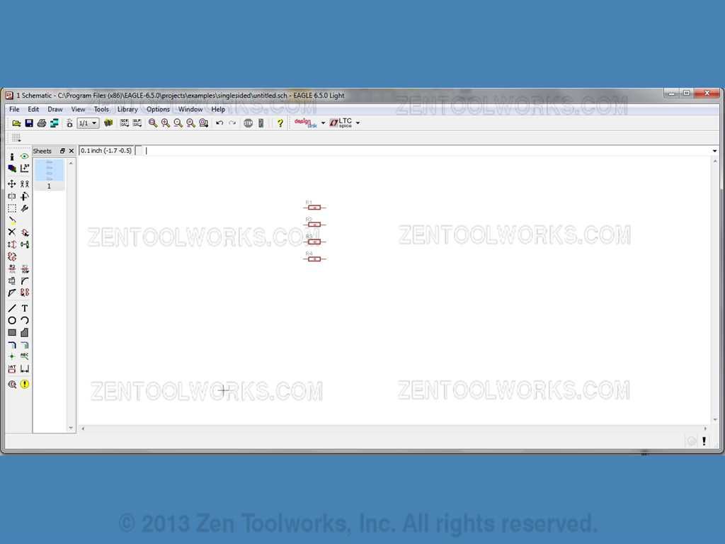
- After placing our four resistors you press ESC to get taken back to the ADD menu.
Part Placement Part 2: LED's
- Now we want to add some LED's to our schematic. From the ADD menu we go to led>LED>LED5MM.
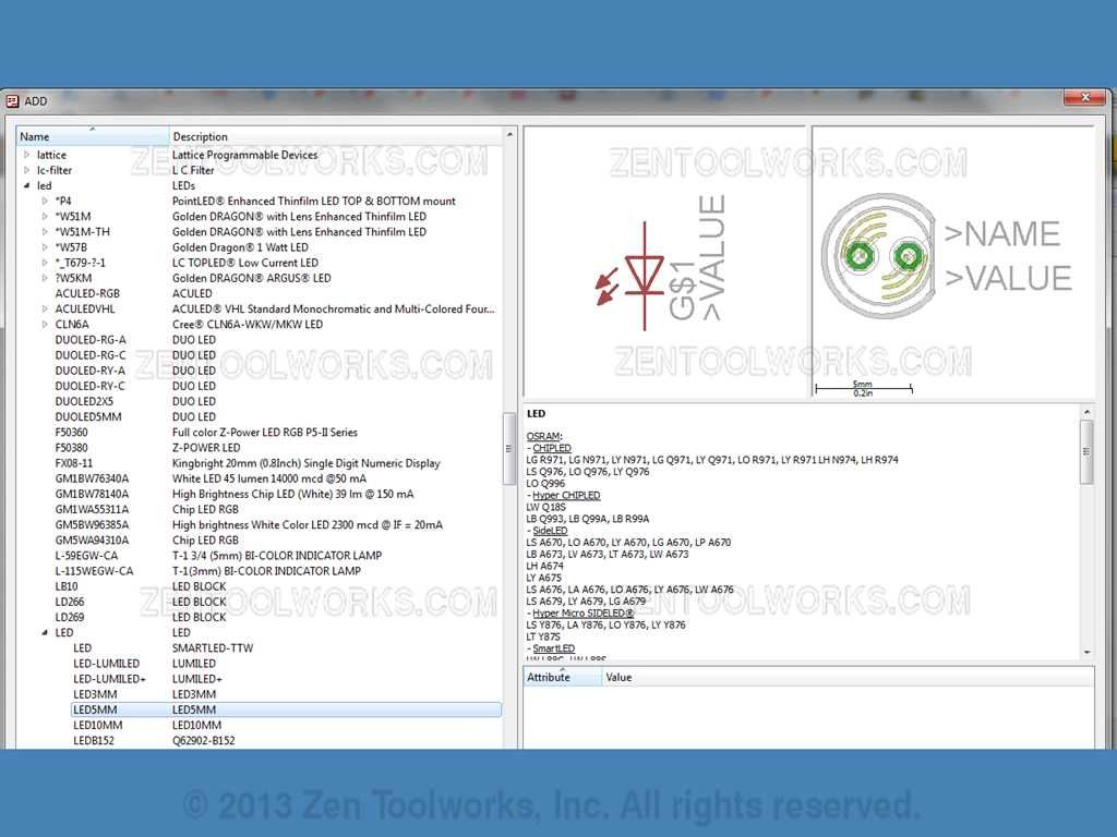
- We then place 4 LED's onto the Schematic.
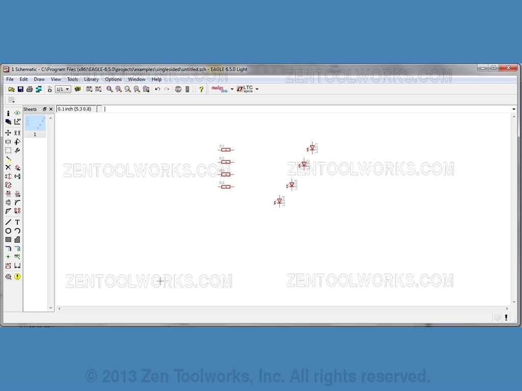
- Now press ESC to be taken back to the ADD menu.
Part Placement Part 3: Switches
- We now want to add our switches to our schematic. We find them by going to: switch-omron>10-XX.
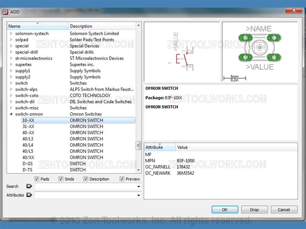
- Go ahead and place four of those switches down and press ESC.
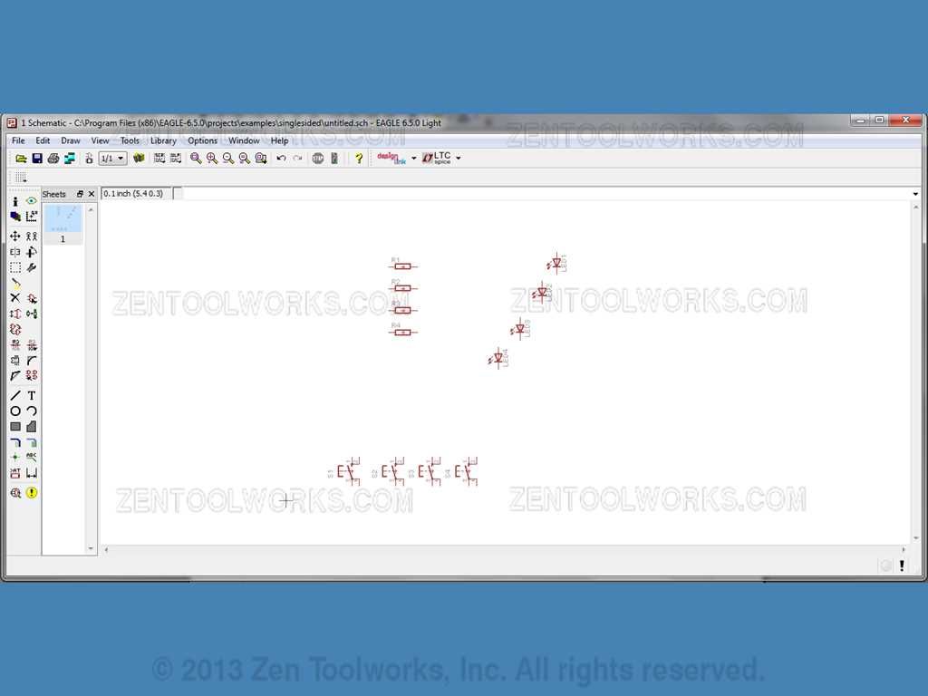
Part Placement Part 4: Connectors to Arduino
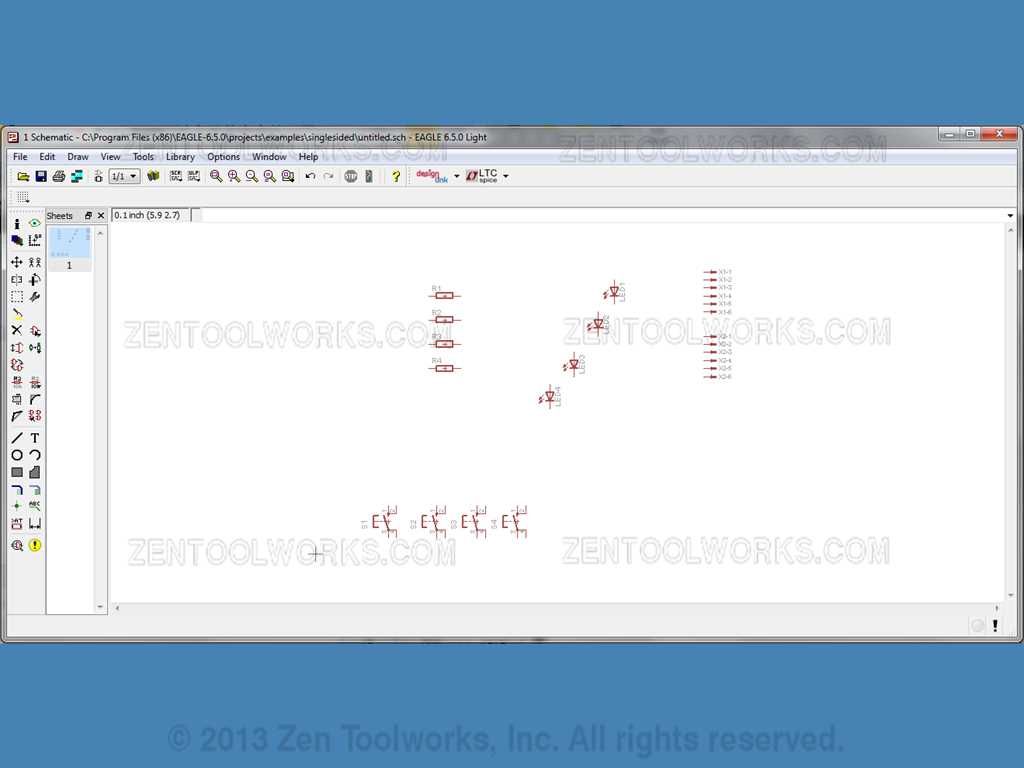
- Now we want to add our connectors to our Schematic. We want to have two 6 pin connectors for Analog and power and we want to have two 8 pin connectors for digital signals.
- First select the 6 pin connectors by going to: con-molex>22-23-2061
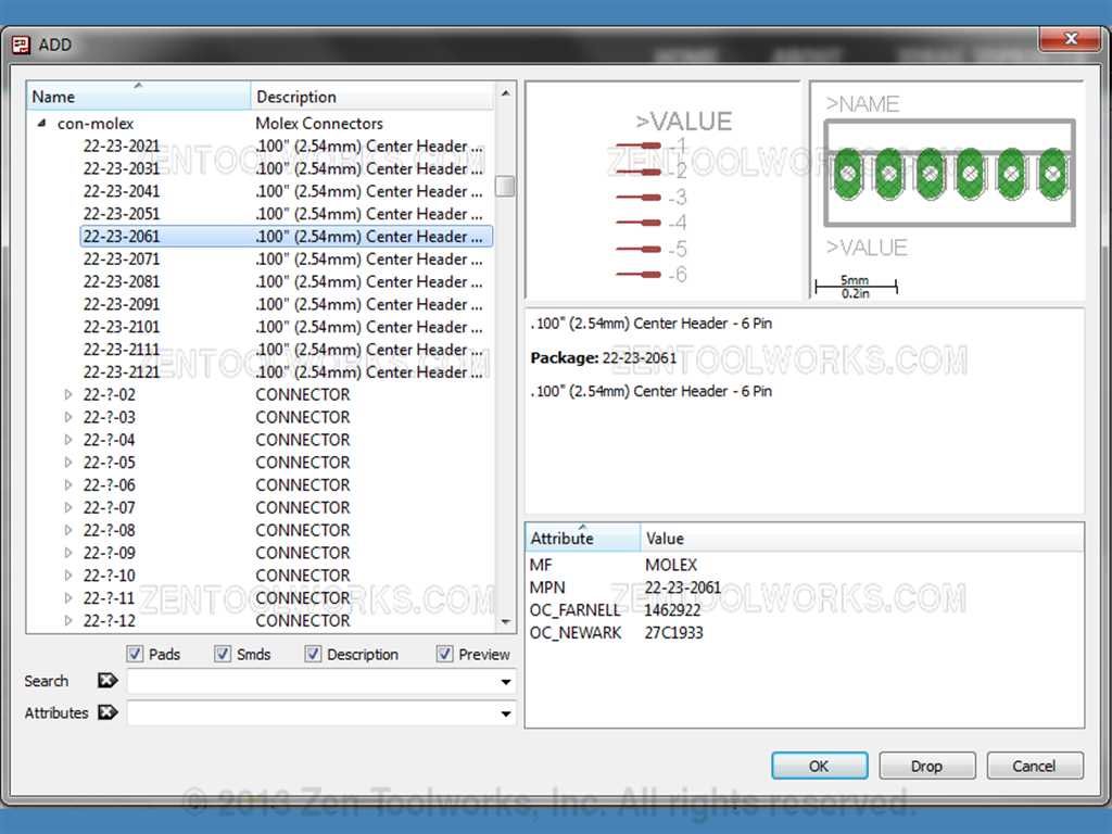
- Go ahead and add two of those connectors.
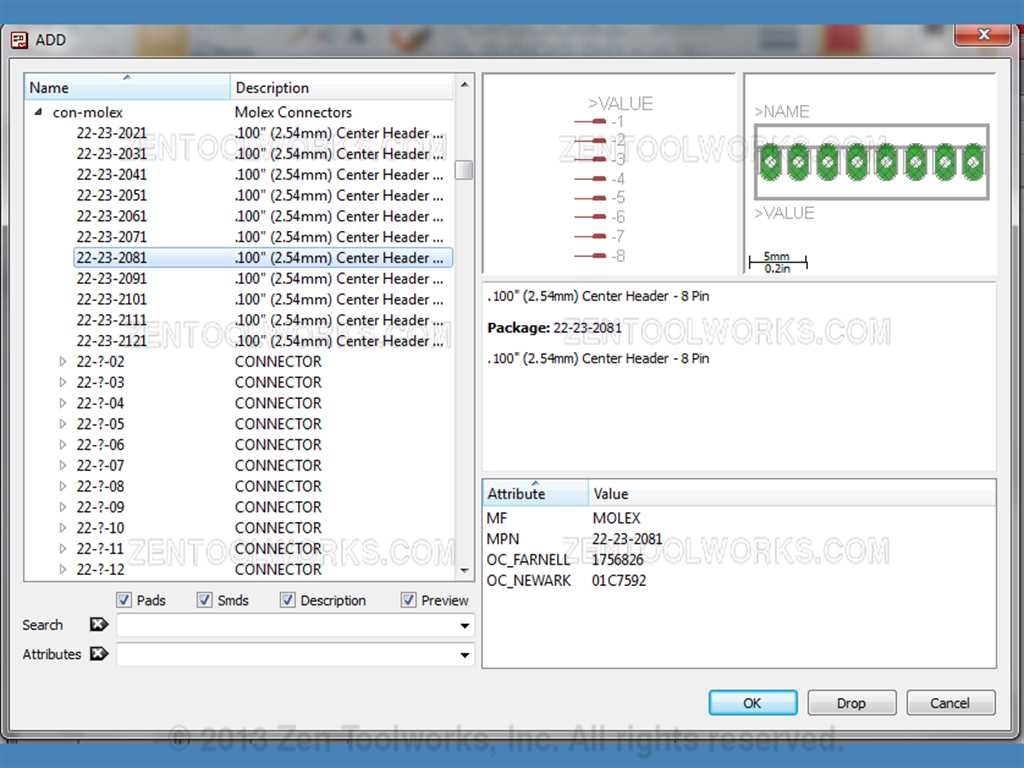
- Now we go and get the 8 pin connectors by going to: con-molex>22-23-2081
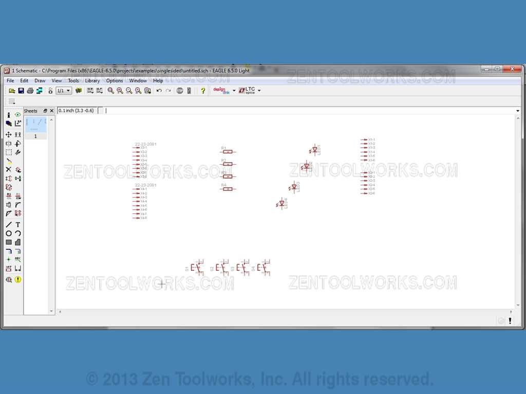
- Now we add two of those to the schematic.
Adding Resistor Values
- Now what we want to do is add values to our resistors. We do this one at a time by right-clicking them and clicking Value.

- For most LED's a 330 ohm resistor is what is needed. So for our value we are going to be inputting 330 Ohm to each resistor on our schematic.

- After we get the connectors placed press ESC twice to exit out of the ADD menu.
Renaming Connectors
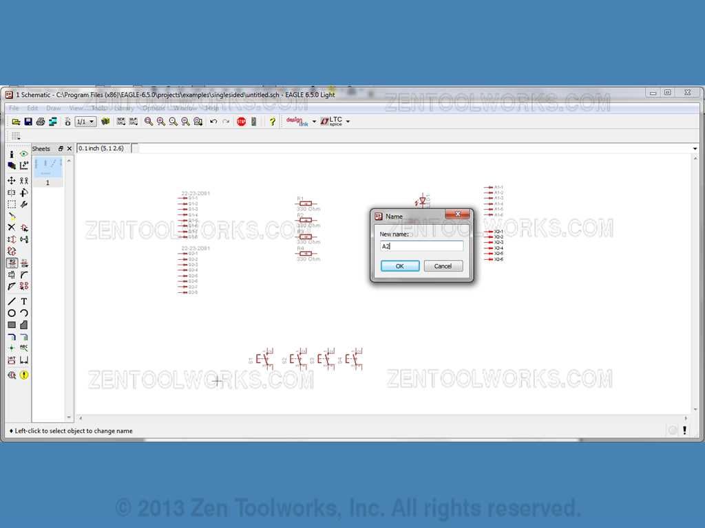
- Now we want to rename our connectors A1 and A2 for our power and analog connectors and D1 and D2 for our digital connectors. We do this by first clicking on the rename tool.
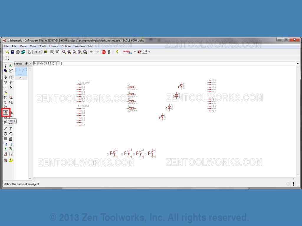
- Next we click on our first set of connectors and rename them to D1.
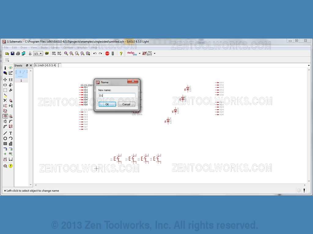
- Do this for the other connectors D2, A1 and A2 Respectively.
Adding LED Grounds
- Now we want to add some grounds to the cathodes of our LED's. We first have to get them from the ADD menu.
- Then we go to: supply1>GND.
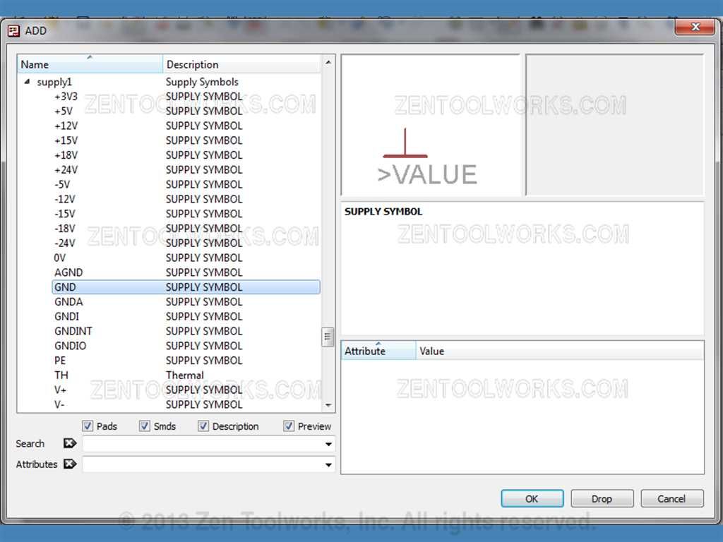
- Now we want to place four of them right below the cathodes of our LED's

- We can now press ESC twice to back out of the ADD command.
Flipping Connectors
- We need to flip the pins around on our D1 and D2 Connectors. We do this by clicking on the mirror command.
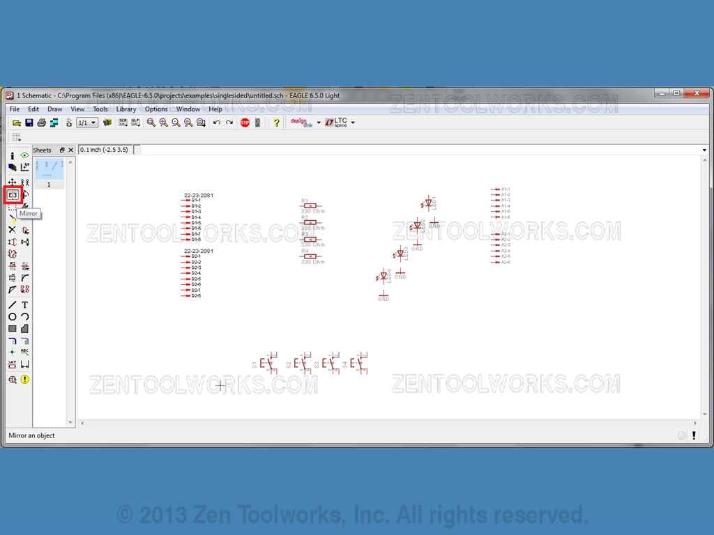
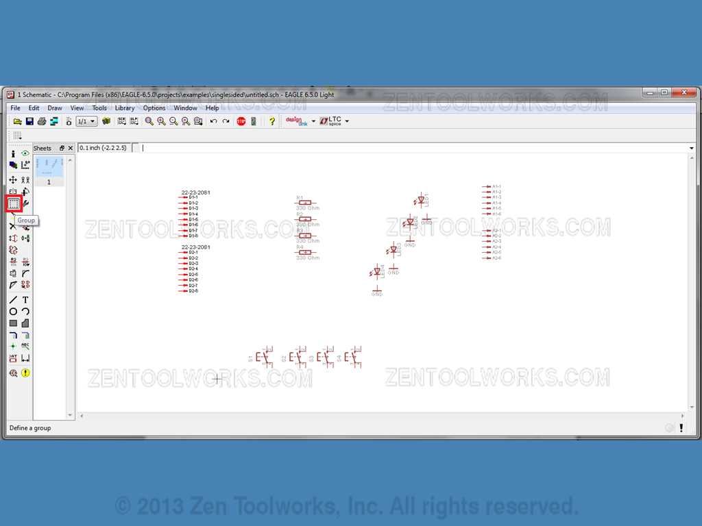
- Next we want to click the Group command.
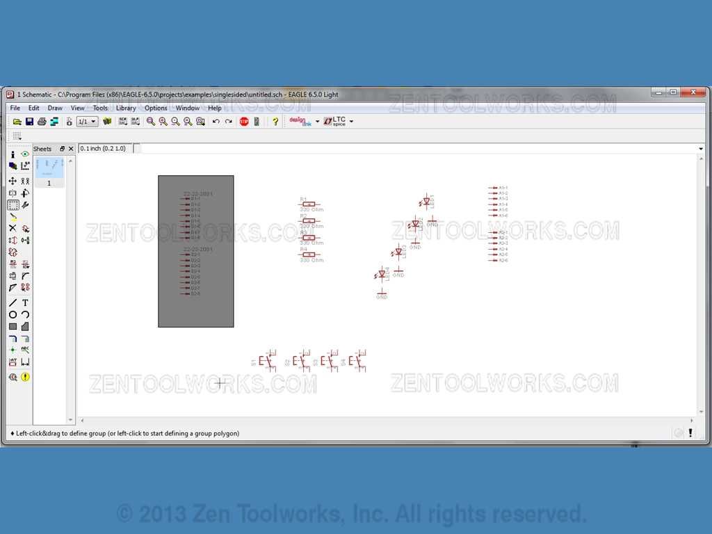
- Then we drag a box over all of the connectors in D1 and D2.
- Next we Right-Click in a nearby blank area and Click on Mirror: Group.
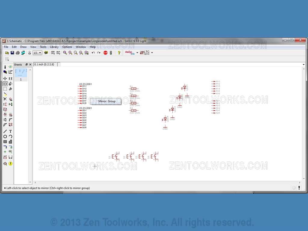
- WARNING: EAGLE will mirror anything to exactly where you clicked. Be careful with the placement.
- If it gets place in an area that was unintentional you can just click Move.
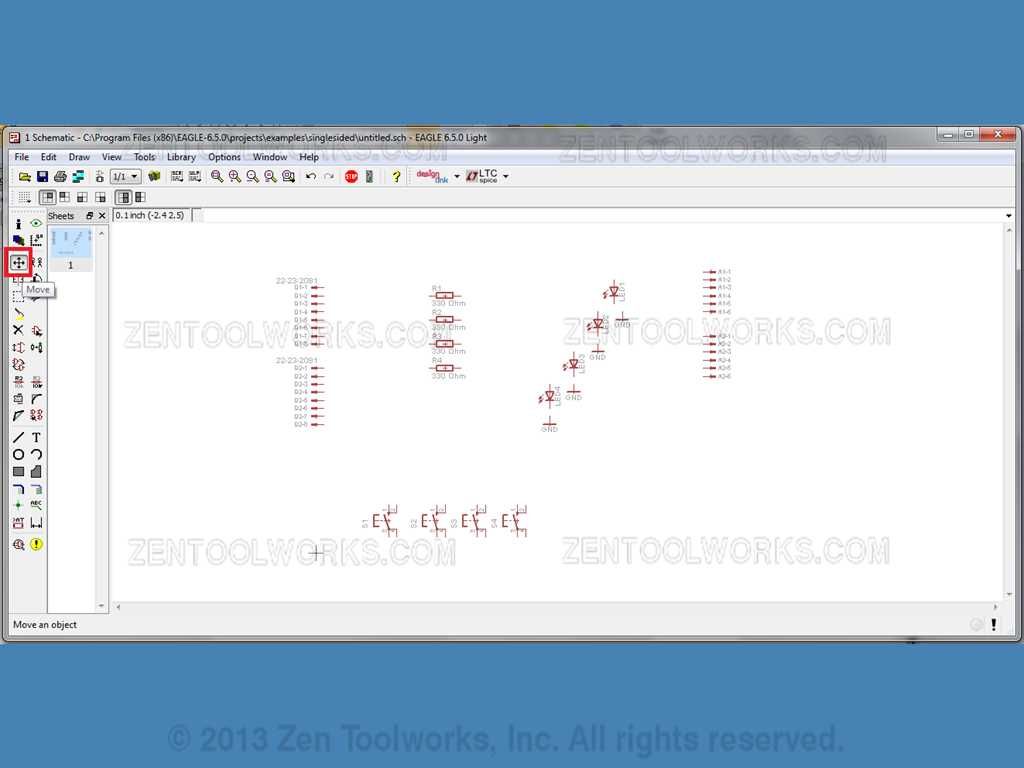
- Right-Click on the schematic, and click Move: Group.
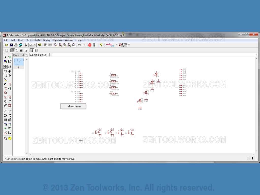
- Then move the connectors to where you want them to go.
Connecting Our Parts
- Now it is time to draw some connections, more specifically we want to connect our LED's to the resistors and grounds along with wiring them into some pins on the connectors. We do this by selecting the Wire button.
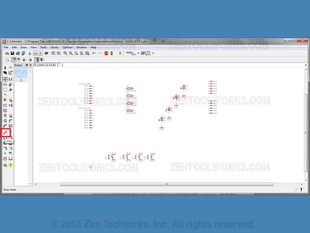
- Once the wire tool is selected we then click on one of the ends of a connector (In this case D1). Then draw a line to our first Resistor.
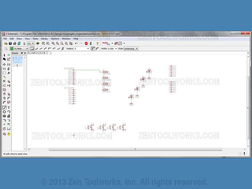
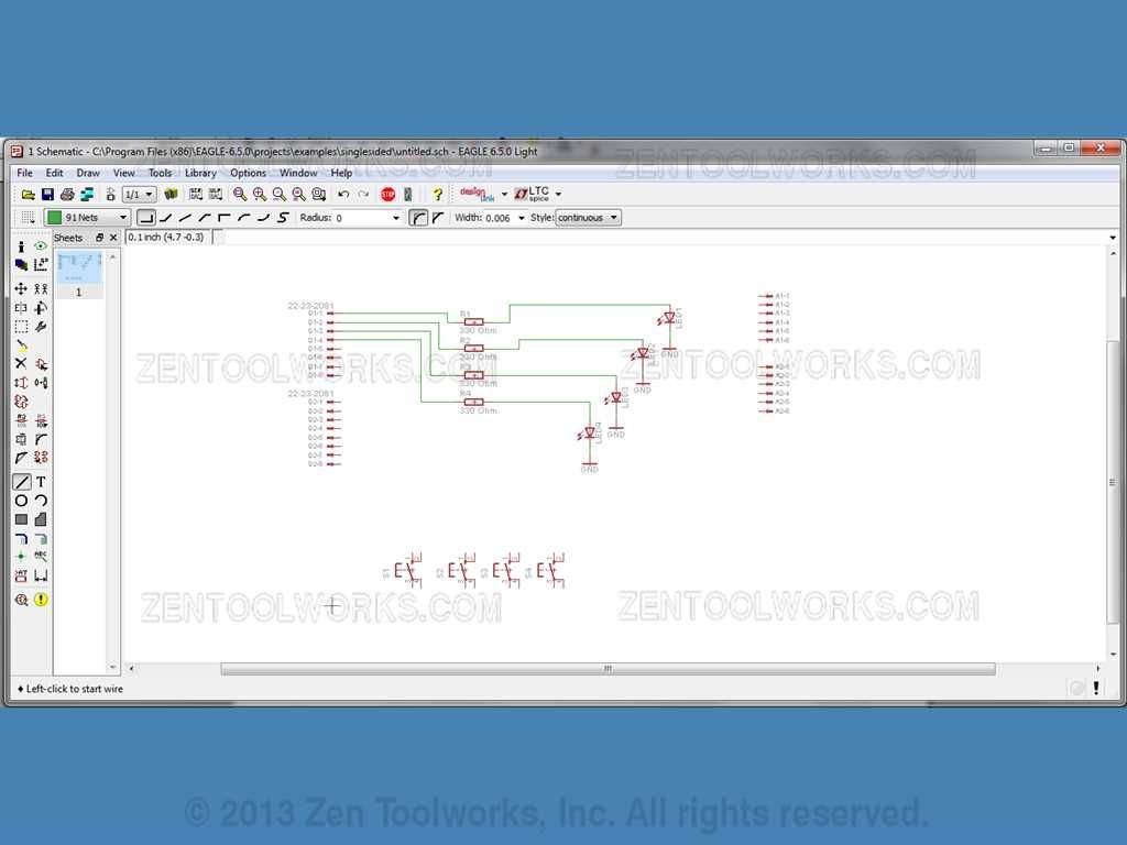
- Please note that to start a wire you click on the start point, any joints you want to make in the wire just simply requires you to click and change direction. Once you connect your intended parts together hit ESC to cancel making more lines connecting from the start point. Repeat this process for each connector to each resistor, then go from resistor to each LED anode, and finally finishing up with each LED cathode connected to ground.
Adding a Few Extras and Finishing Connections
- Now that we have all of our LED's ready to go we then can focus on the switches. We need to add more grounds and resistors to them before we can do anything else. Use the ADD tool go to: supply1>GND, for your grounds and resistor>RE_U>RE_U_0207/10 for your resistors. You can add them to the schematic under the switches similar to what is shown. Don't forget to give each resistor a 330 ohm value.
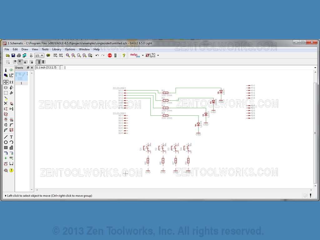
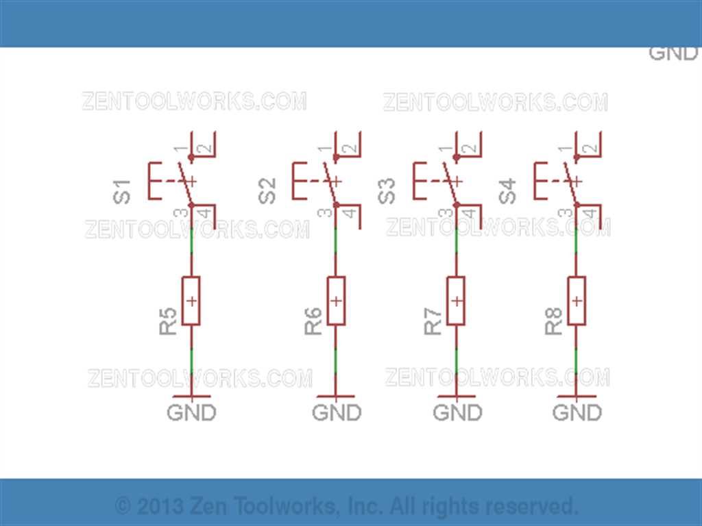
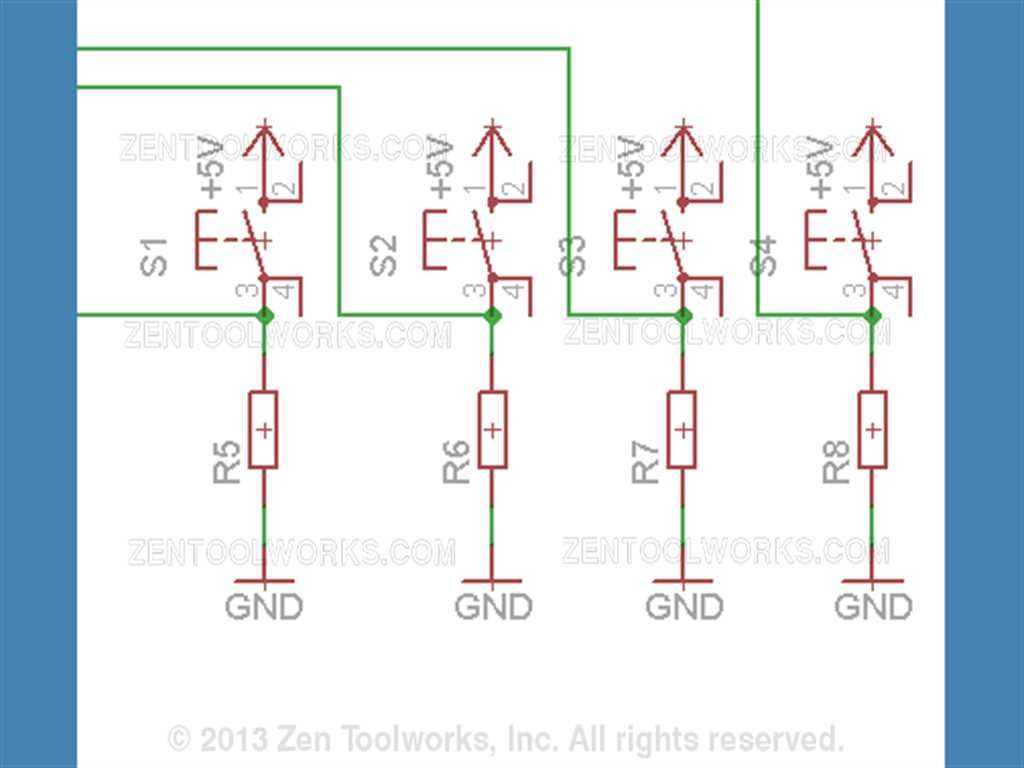
- Next using the wire tool from before connect the grounds to the resistors then the resistors to leg 3 on each of the switches.
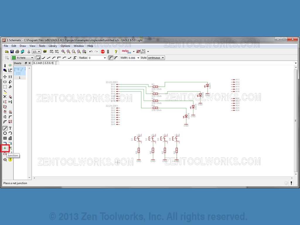
- Now we need to add some junctions to each of the Pin 3's of our switches. We just have to click the junction tool.
- And now we just click each Pin 3 on our switches.
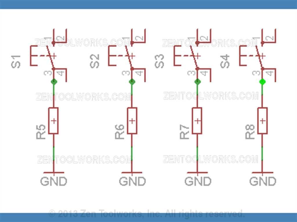
- Once you get the junctions on the schematic, then you go ahead and click on our wire tool. Now we need to connect each junction to some connectors.
- We are going to do this by having S1 Pin3 connected to D2-2, Then we have S2 Pin 3 connected to D2-1, S3 Pin 3 to D1-6 and finally S4 Pin 3 connected to D1-5.

Adding Power to Our Schematic
- Now that we have our switches grounded we need to get some power to them. We go and click on our ADD button and go to: source1 > +5V.
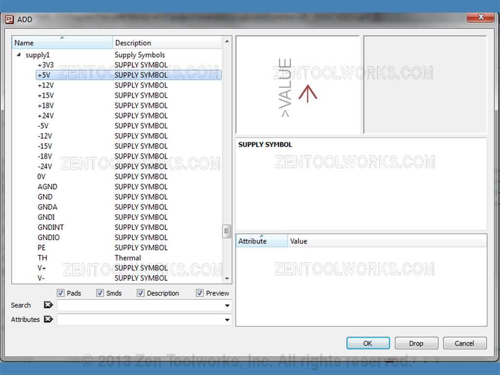
- We then place a source above the Pin 1 of each switch.
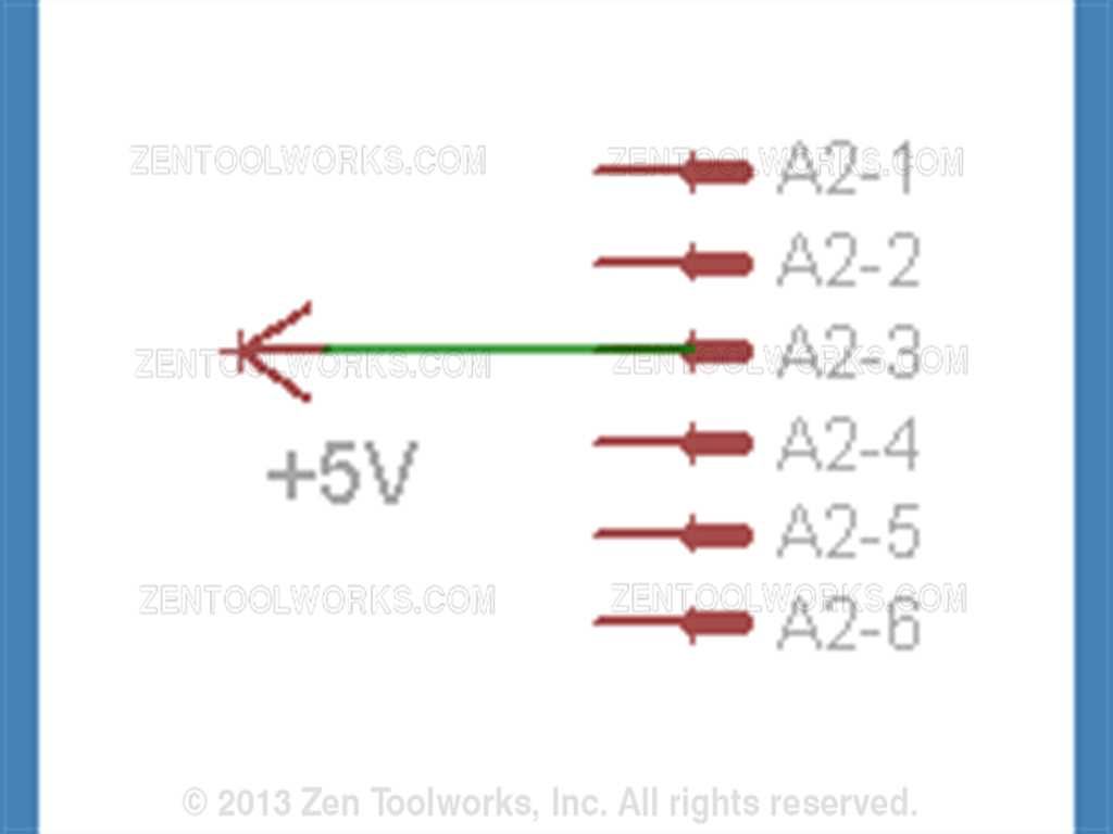
- Now we can also put a source while we are at it by A2 and connect it to pin A2-3. You can rotate the placement of parts before inserting them by Right-Clicking before placement.
- Now we can go and get an GND from the ADD tool. Place it near A2-5. Add a Junction to the GND then connect A2-4 and A2-5 to the junction using the wire tool.
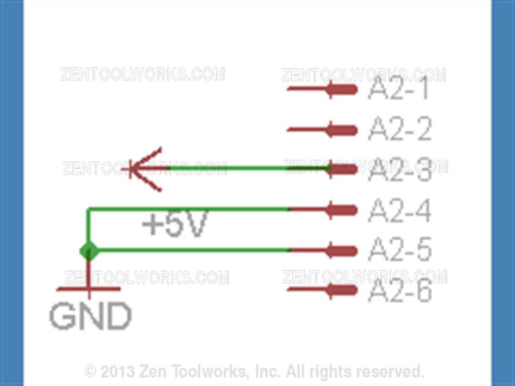
- Now our schematic is complete!
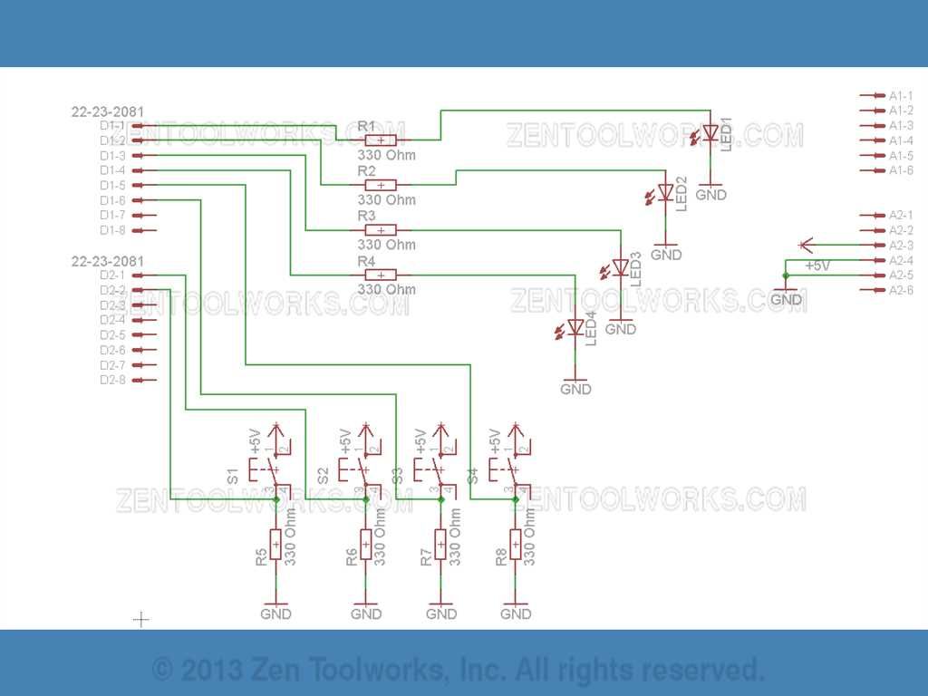
- You will notice most of the Analog pins and half of the Digital pins aren't connected to anything at all. This is intentional by design, we don't need to connect every pin, just enough to drive the parts we need and feed it the 5v of electricity.
Error Checking
- Now that our schematic is done, we go to Tools>ERC to check our errors.
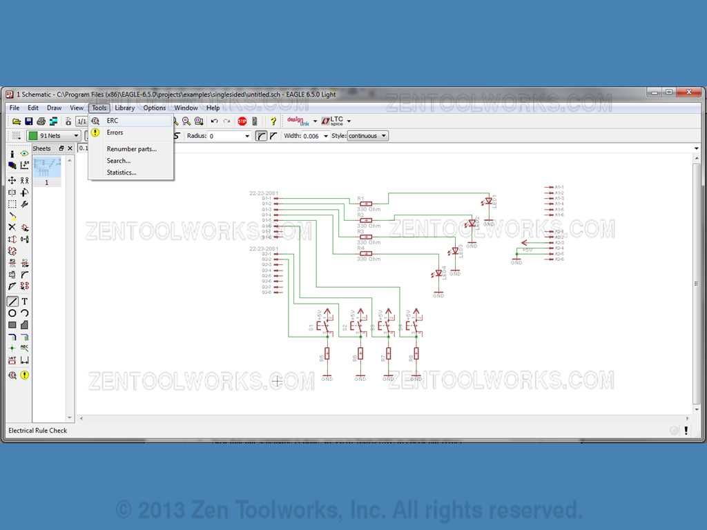
- You will notice a lot of errors even though we did the schematic correctly.
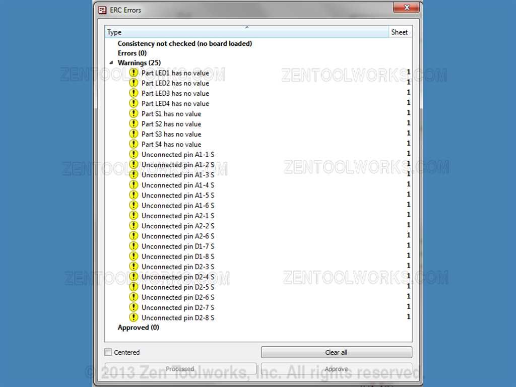
- All of these errors can be disregarded because as it was mentioned before not all pins need to be connected. As an additional note you do not need values for the LED's and the Switches. Click each individual “error” and press the Approve button for each one. Run the error correction one more time to make sure nothing else is wrong. Watch out for “overlapping wires” and other errors. The ones in the picture above are the only ones we approve.
Board Creation
- Now that we are done error checking we can now draw the circuit board. We do this by clicking the tool up top called “Board”.
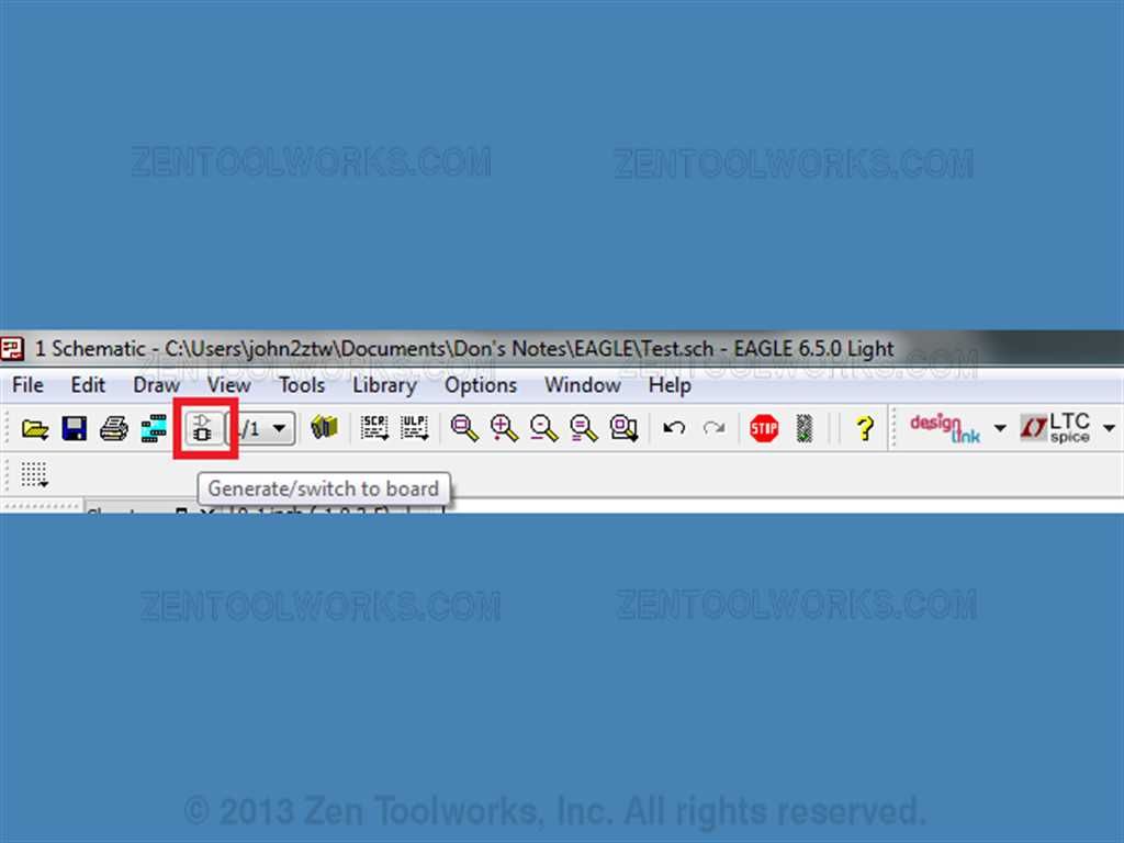
- You will get a message telling you that the board doesn't exist and asking you if you want to create from the schematic. Click “Yes”.

Circuit Builder Setup
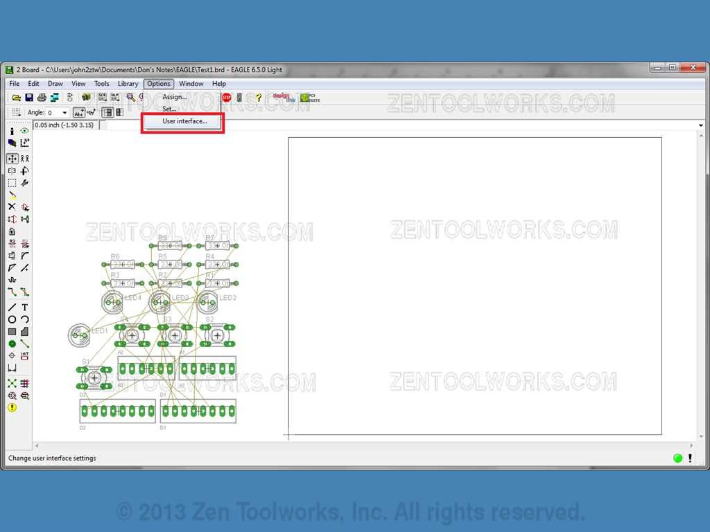
- For this part you will want to change the color of your background to make it easier to see all of your parts before we move them right on to the board. You do this by going to Option>User Interface...
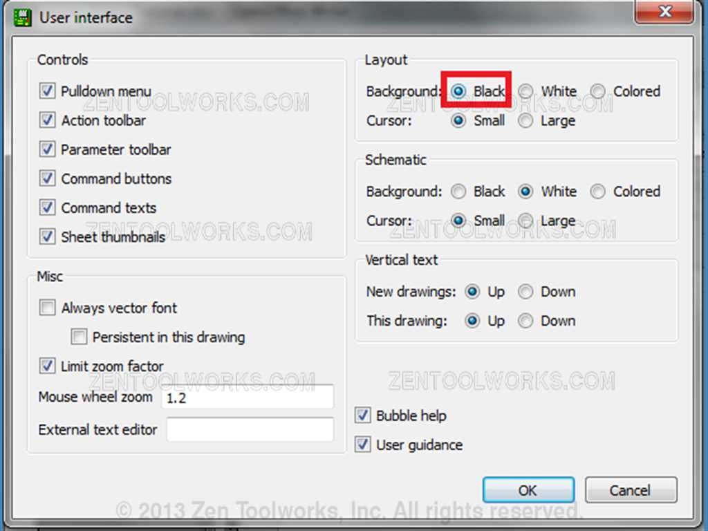
- Now go to the layout area and click the dot next to Black.
- Now press OK and we get the screen below.
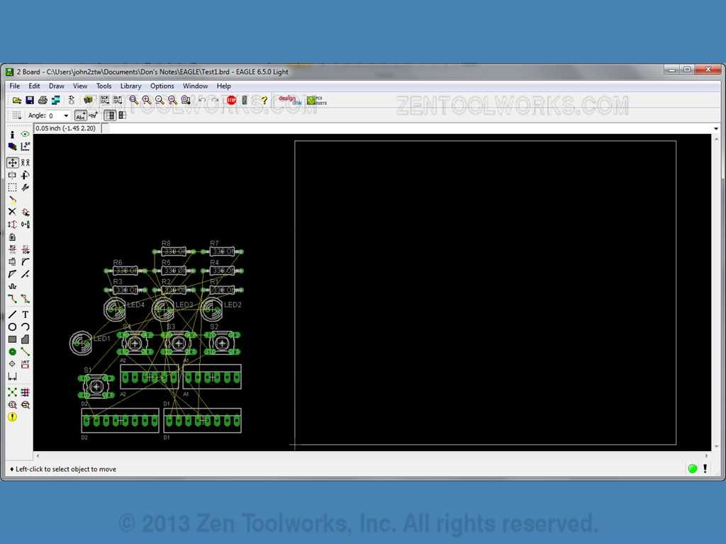
- Notice how we have our parts in a jumbled mess right next to a box on screen. The box is where our circuit goes, we need to put those parts in a logical pattern for our CNC machine to not only mill it out, but be able to place the circuit board on an Arduino and have it function properly. For the most part this is an anything goes affair with all of the other parts, BUT the pin alignment is key for our connectors. We need them a specific distance apart and have the A1 and A2 connectors parallel to the D1 and D2 connectors. The rest of the parts go in-between the two rows of connectors. To aide us in placing the parts we will utilize the Grid feature which we access by clicking View>Grid...
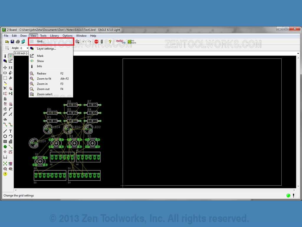
- Click “On” in the display box. We need to then change the size to 5 mil, so that we have more precise movements with our parts.

- We do this by first clicking on the inch drop down box and selecting mil.
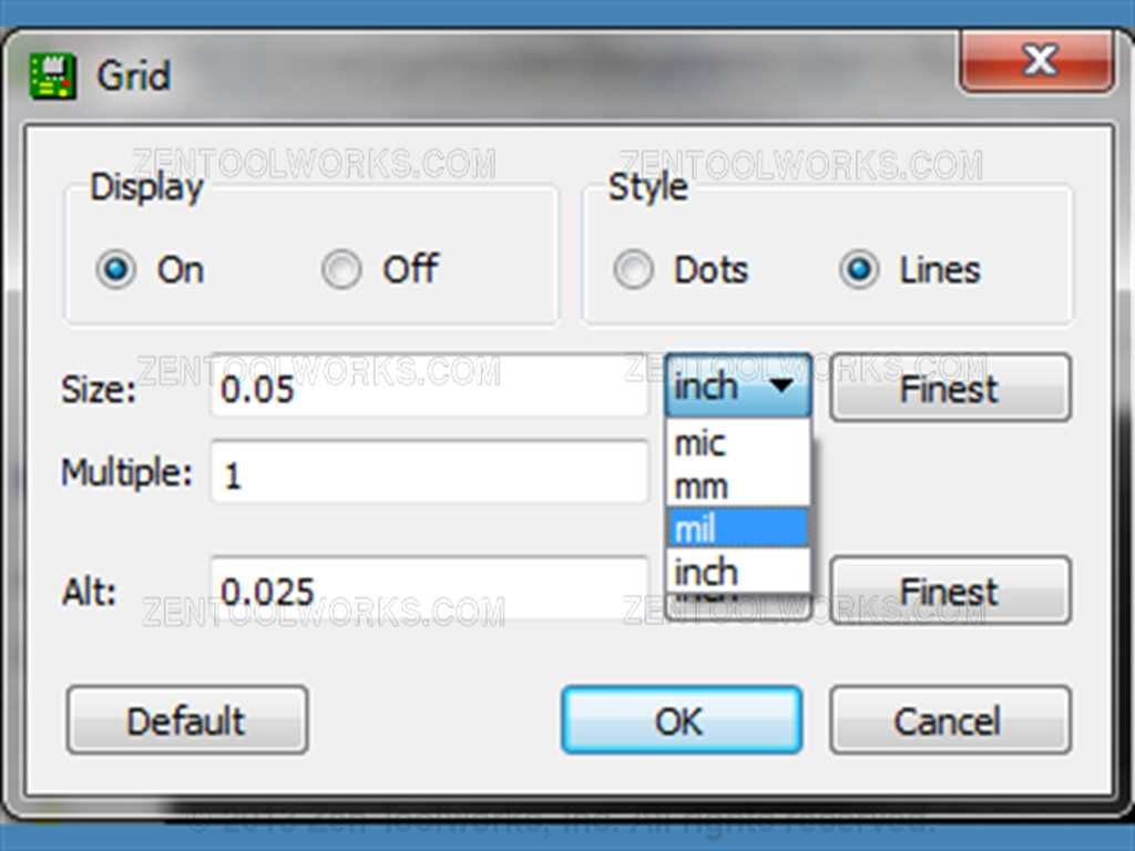
- We then change the number in the size box to simply 5

- Now hit OK. What this does is allows our mouse to move in areas divisible by 5 mil. Now we are able to place our parts. The most tedious part of this exercise is manually placing the pin packages onto the area. We make this a tad easier to do by having the 5 mil grid in place. For this tutorial we are doing it manually so that we can display how part placement works. In the future you can use many different methods of doing this such as importing the pin layout for an Arduino Uno by downloading it from the manufacturer's website, (The folks at Arduino.cc provide their microcontroller schematics in EAGLE for you to download.) or another website such as Adafruit which have their own libraries with Arduinos already on them.
Precision Part Placement
- Now we are ready for placement of our pin packages. The most important thing to note is the upper left-hand corner. This displays our current position in Mil. We are going to use this to measure between our connectors to make sure we get it as precise as possible between them. We are also going to be using the right-hand white line as a reference.
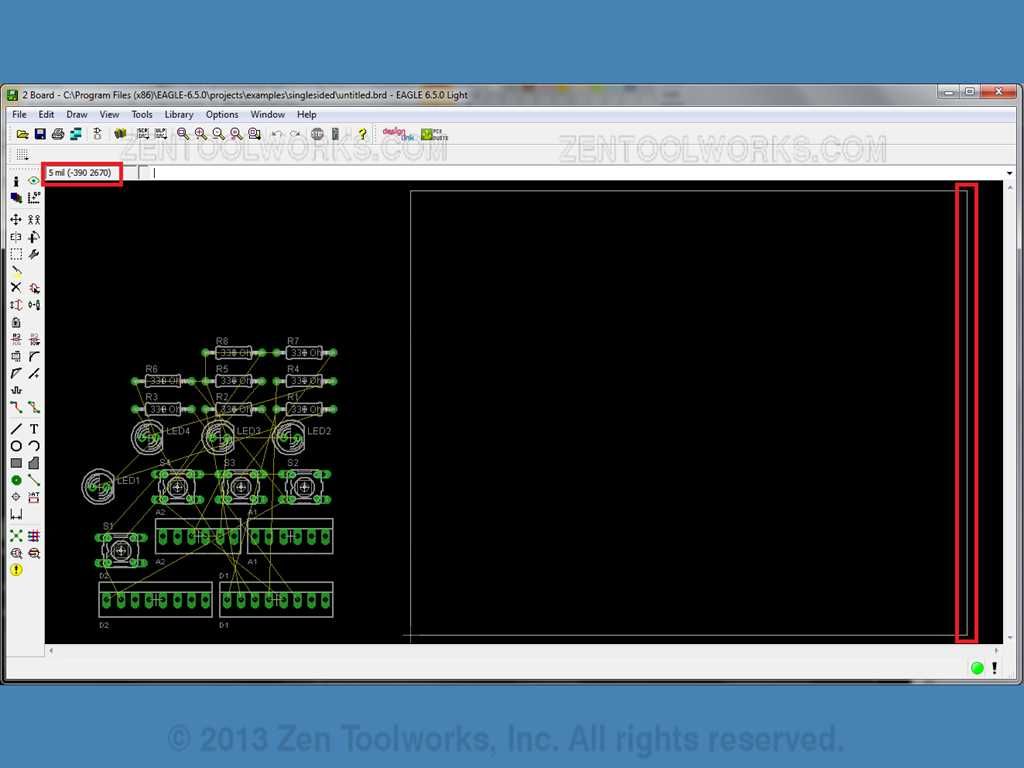
- Note that the number on the left is correlating to the position horizontally, or the X-Axis, and the number on the right correlates to the vertical position, or the Y-Axis. We are going to start by first selecting the group tool. Then we are going to highlight D1.
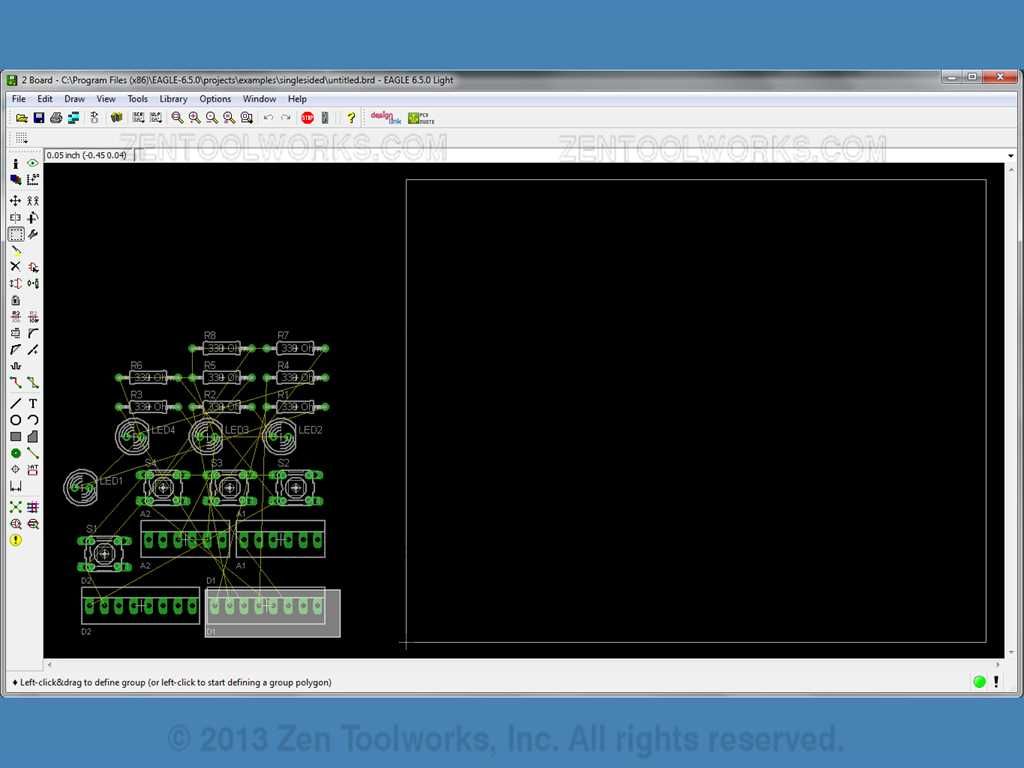
- Now we are going to position our cursor in roughly the center of the right-most connector, as best as we can and Right-Click. We then want to click Move: Group. This is an important step as all of the measurements I have taken of the Arduino Uno board are based of the position of each Right-Most pin in relation to each connector package and the Right-Most white boarder. We then move the package until you get the center Right-Most pin roughly 95-100 mil from the right-hand side of the white boarder. Try to get it pretty snug to but not touching the top-most white boarder.
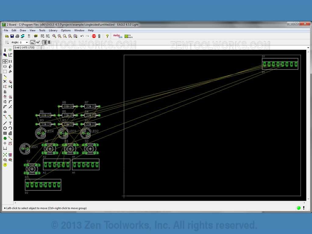
- Now we want to move our D2 connector package. We want it to be lined up right next to the D1 package we had just placed. Also we need to flip the connector package around so that all of our connected pins are lined up. We also want to keep the center of the last pin of D2 160 mil away from the center of the first pin of D1 to maintain the alignment of our Arduino board. Note the pin locations of your digital I/O ports on the Arduino. You want to make sure you have all of your pins aligned according to your schematic to agree with the design of the Arduino.

- We also don’t want our connected pins to be placed on TX, RX nor do we want them placed on AREF or GND. To rotate the connector package you first highlight the connector package you want to rotate. Then you click the plus sign looking button, which is our rotate button.
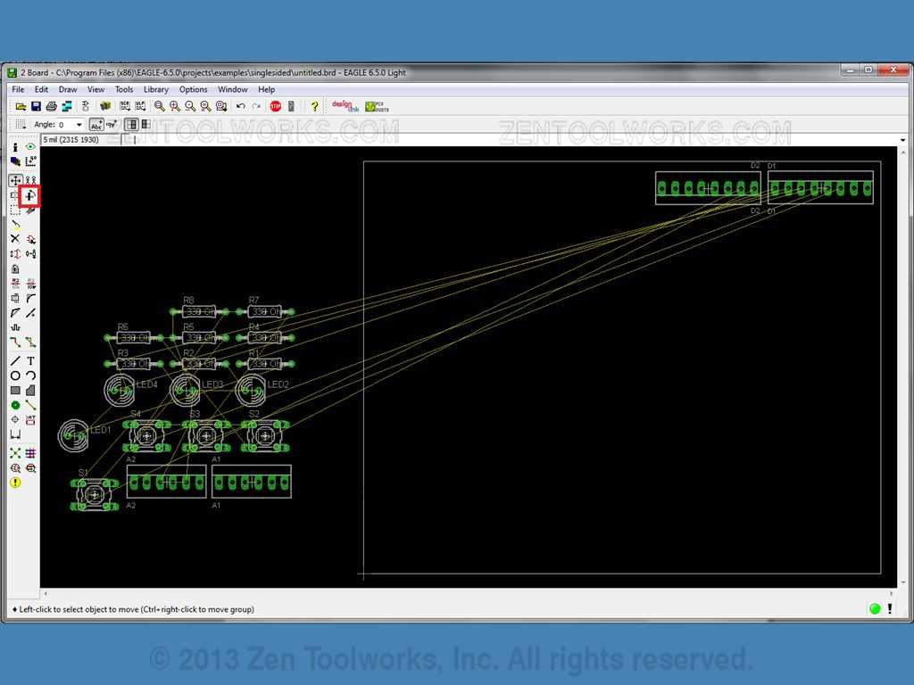
- We then Right-Click the package and select Rotate: All. Repeat one more time to get the desired result. We then move the package by highlighting the package again then pressing the move button. After that we right-click the center of the right-most pin and select Move:All. Then we move it to the desired location on our layout.
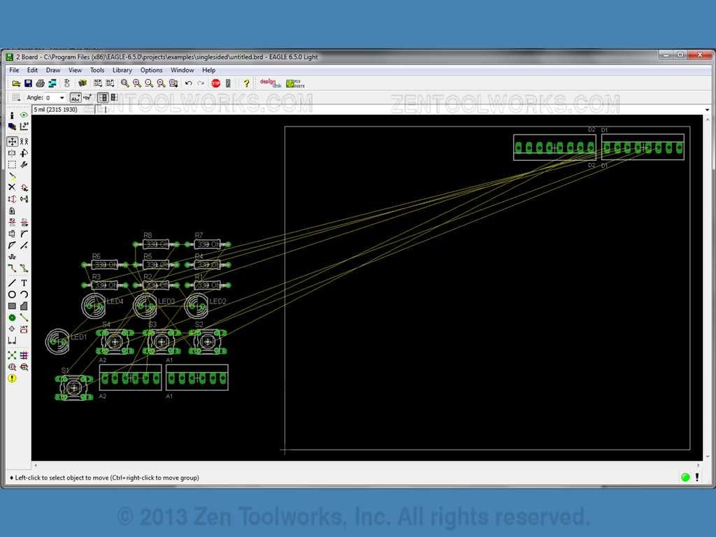
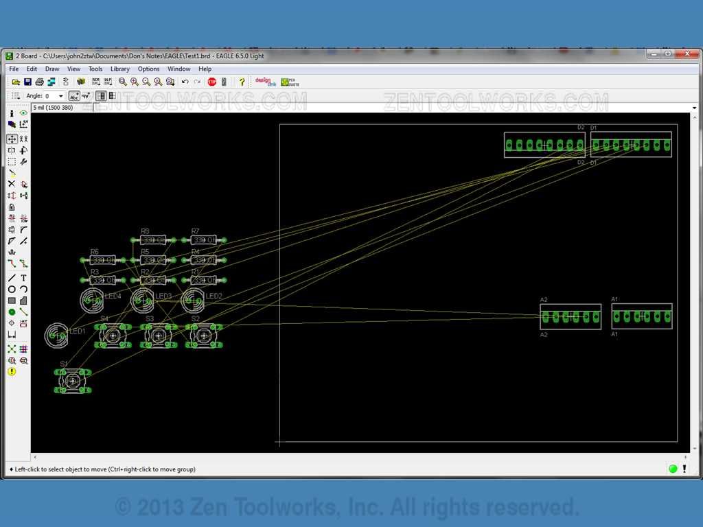
- Next we are going to want to position A1. This needs to be placed in parallel with the two connector packages already in place. A1's last pin also needs to be the same distance away from the right-hand line as D1's is. Which is 95-100 mil away from the line. Additionally the last connector of A1 needs to be about 1895mil away from the last connector of D1.

- Now that A1 is in place we want to line up A2 right next to it. We need the center of the final pin of A2 to be 200 mil away from the center of the first pin of A1.
Finishing Touches and DRC
- Now that our connector packages are in place we can now begin to place the other parts in this schematic. The only vital measurements we needed were the connector packages. Once you get used to moving things and placing them you can just as easily use the previously mentioned packages for arduino to make things a lot easier. We can place the parts anywhere as long as they are between our two connector packages. But we do want it to look nice so try to keep parts in line with each other.
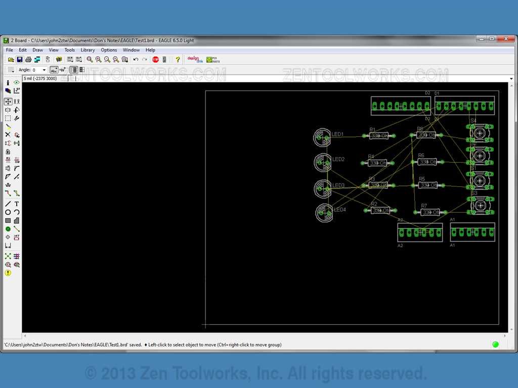
- Now that all of our parts are in place we want to make the white box around all of our parts a bit smaller to match the size of the board we want to make. You can do this easily by clicking the left-hand line and dragging it inward. Then we want to click the bottom line and drag that one inward as well.

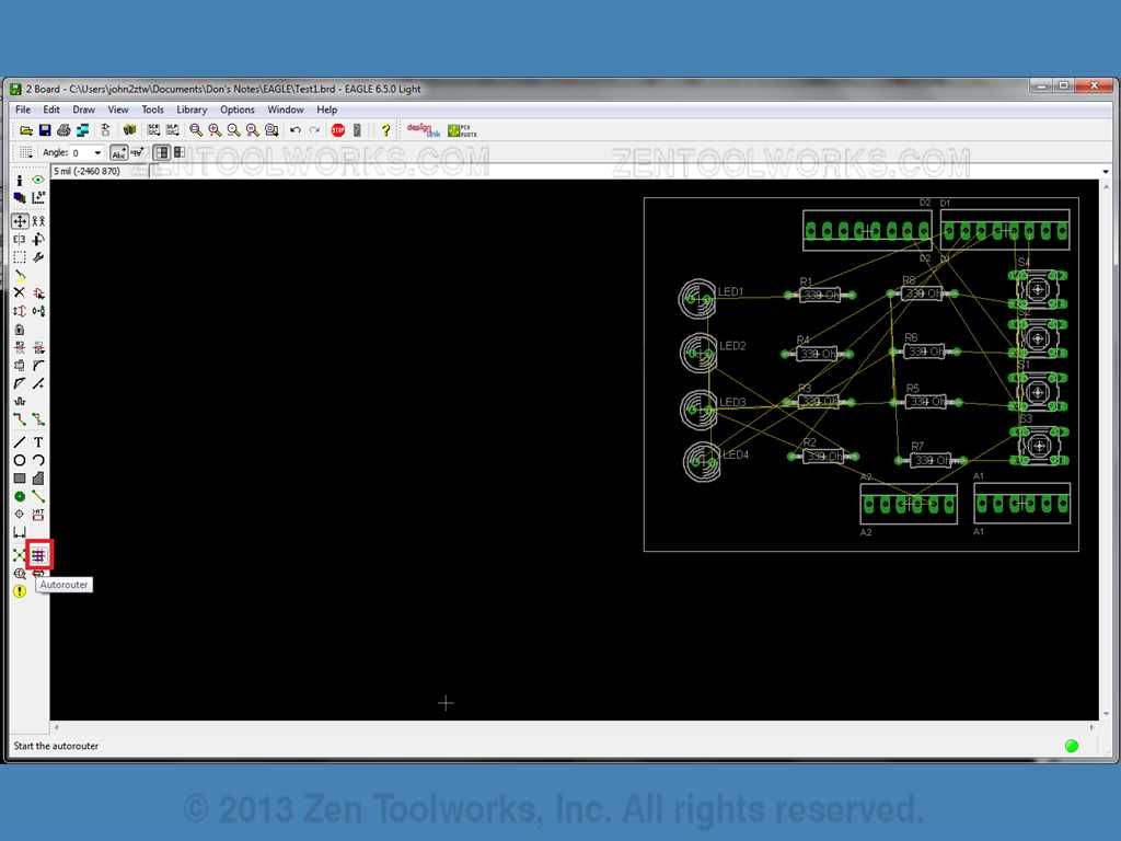
- Now that our board is ready we can now route it to get it ready for where the CNC machine is going to cut. So we are going to use the Autorouter function to accomplish this goal. It is the button that looks like a mesh of blue and red wires.
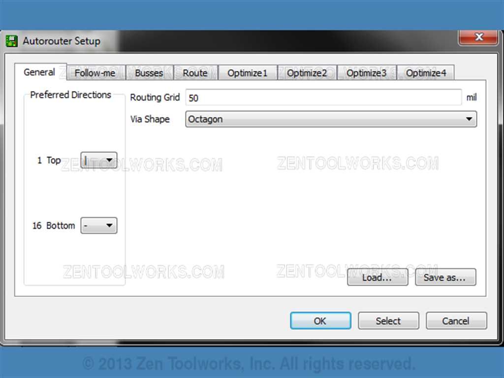
- Once you click the autoroute button you will get a display of all of the options it has. The freeware version of EAGLE only allows you to do two layers which is fine for this exercise. You should open up a window like this:
- For this exercise we are just going to press OK. You will notice that not all of your wires may be routed like so:
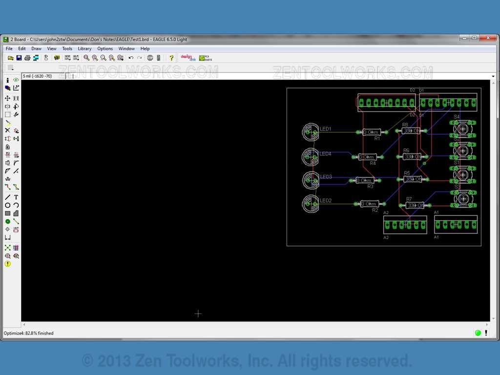
- This is easy to fix as you just need to slightly move parts around, maybe even flip some of the resistors. Then you use the Autoroute function again. If you still have yellow lines you just keep adjusting and trying again until you have everything connected with either a blue or red line.
- The board design is now complete. From here you have many options you can do such as send off this design to have it professionally made or, if you happen to have a tabletop CNC machine you can upload it to PCB-GCode and have it make the code needed to have your machine mill it out. One thing you might want to do is move the entire board to where the top-right corner is at 0 on the X-Axis. This makes it so that it is much easier to follow it in GCode when the time comes for that.