Probing and Milling a PCB Using an Arduino Based CNC
by zentoolworks in Circuits > Arduino
86369 Views, 142 Favorites, 0 Comments
Probing and Milling a PCB Using an Arduino Based CNC

Until recently PCB probing using an Arduino based CNC machine was but a mere dream. Thanks to the folks at Chilipeppr.com we now have a web-based tool bench for all of our Arduino based CNC products. The best part; it’s free and it also comes with an on-board auto-leveller for those PCB jobs we want to do.
Materials Needed:
- Blank Copper PCB
- A PCB schematic in G-Code
- An Arduino Based CNC machine such as the Zen Toolworks 7 x12
- Double Sided Tape and masking tape for the probe leads
- Two wires for the leads.
- GRBL version 0.9g
- The JSON loader for Chilipeppr
Note:
For this tutorial I am going to be using the mentioned Zen Toolworks 7x12 CNC machine with the Arduino stepper motor package, which can be bought either on Amazon.com or at Zentoolworks.com. Theoretically this tutorial can be followed using any Arduino based CNC machine but mileage and machine specifications may vary.
Setting Up Our Arduino
Step 1:
- The first thing we need to do is flash our Arduino with the latest developer version of GRBL, which is 0.9g as of this writing.
- We also need to get a version of the XLoader which you can get here: http://russemotto.com/xloader
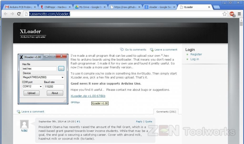
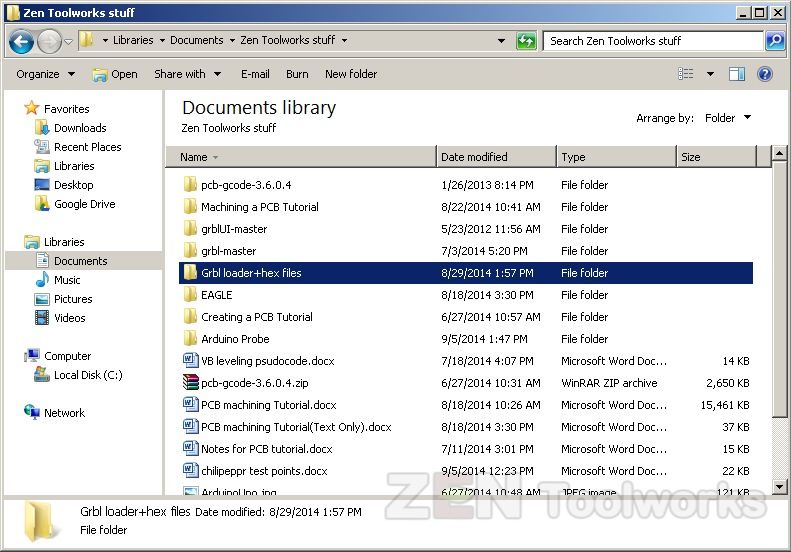
- After you download this you want to then want to unzip it into a folder that is very easy to find.
- The GRBL 0.9g can be attained at: http://russemotto.com/xloader/
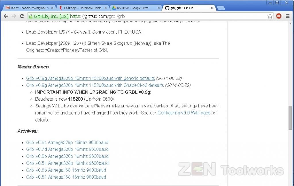
- Click on the link with the generic defaults.
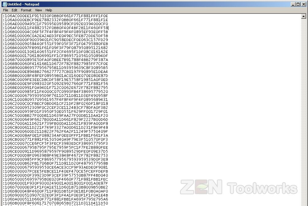
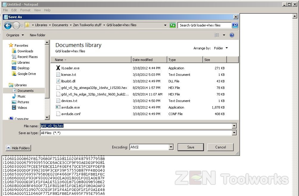
- You will get a screen with a bunch of numbers and letters. Don’t panic this is just HEX code. You highlight everything on that page and right-click then click copy.
- Then you will need to paste it in Notepad.

- Then you will need to click File > Save As, navigate to where you unzipped the XLoader then give it a name that ends with .hex.
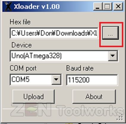
- Now that we have our .hex file we then open up the XLoader. The first thing we want to do is click the box with the three dots on it.
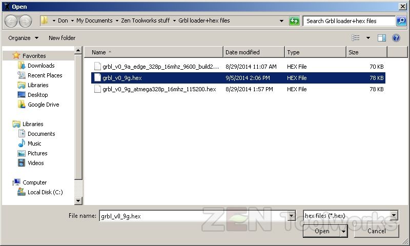
- Next we want to navigate to our new .hex file.
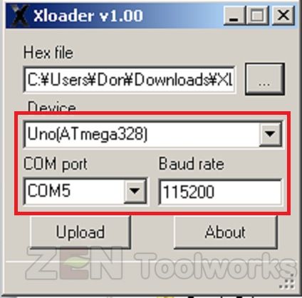
- Now we want to make sure that all of our settings are correct. XLoader automatically detects which port our Arduino is connected to but we need to make sure that we have the correct Arduino set in. In this case we are using an Arduino UNO. Also worth noting that this version of GRBL runs at 115200 baud rate instead of the old 9600 so that needs to be set as well.
- Now that we have all of our settings correct and our .hex file ready we can click Upload to install the firmware.
Chilipeppr Setup
- Now that we have the Arduino to our system set up we then can navigate over to chilipeppr.com/grbl · You will get a screen much like this:
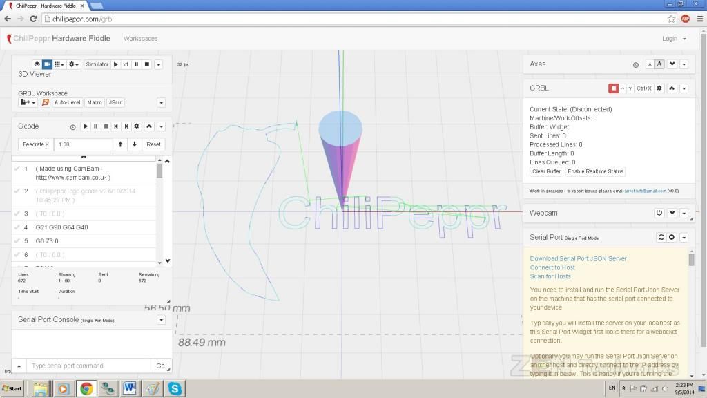
- The first thing we want to do is click on the link that says: “Download Serial Port JSON Server” · This is important because in order for this website to “see” your Arduino it needs to be able to link up to the Arduino itself, the port JSON server allows this communication to take place.
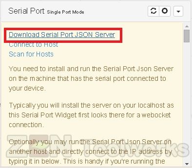
- Once you download it, you are going to want to unzip it into a file that is easy to find because you need to activate that before doing anything.
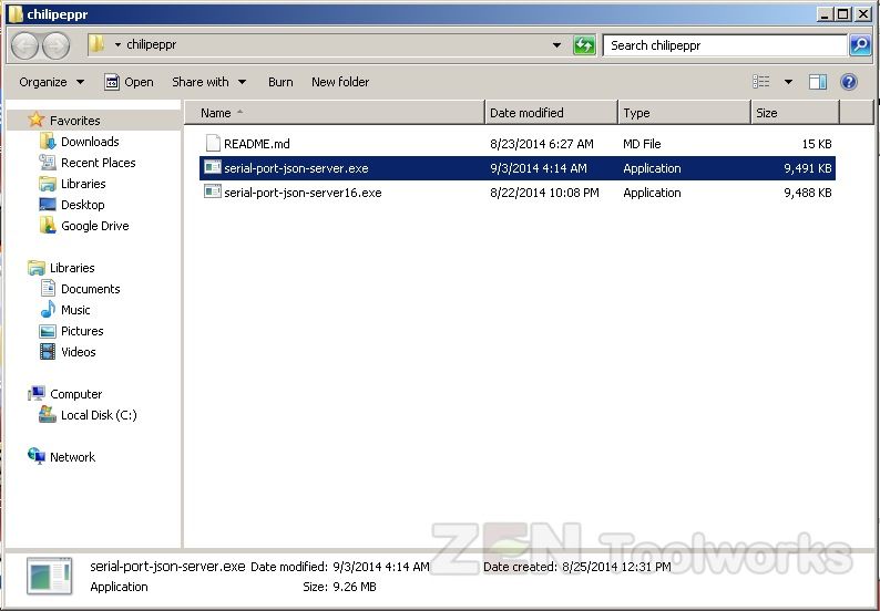
- Open up the Serial JSON server file we just unzipped. You should get a black screen like this:
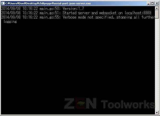
- Now that we have our JSON serial port server up we then make sure our Arduino controlled CNC machine is all plugged in.
- Once you have that taken care of you can press the refresh button on the Serial Port Menu.
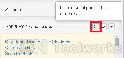
- Now that it “sees” our Arduino, we select the GRBL on the dropdown menu, put in that the baud rate is in fact 115200 and then click on the check mark.

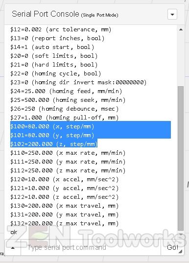
- Now we have to reconfigure our Arduino for our CNC, there are a bit different commands for the new GRBL 0.9g but they are listed for convenience. (Note: For this tutorial I used the previous version of the JSON to have it hold the commands still without streaming. This is mainly for tutorial purposes.)
- Highlighted are the settings I used for the Zen Toolworks 7x12 CNC Machine. Different machines may vary.
- Go ahead and take the time to position your bit where you want to have your Zero be. All G-Code Commands work and GRBL added a few new ones to help us out with this task.
Setting Up Our Arduino Shield
- Now that our program is set up we then have to create a probe. By default the Zen Toolworks Arduino motor shield does not support the new pin used for probing.
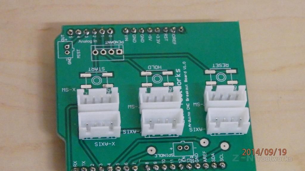
- Since the latest GRBL now supports probing by the way of two new commands, g28.2 and g38.2, they have also allocated as of the 0.9 release that Analog pin 5 of the Arduino is to be the probe.
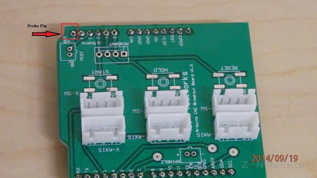
- So what we must do is modify the Arduino shield to support our probe. It is as easy as soldering two wires to the shield. We need to solder one as our lead on pin 5 and another to any of the GND pins.
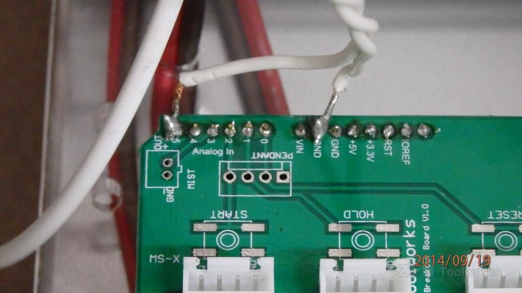
- To help prevent excess noise that may trigger our probe prematurely we go ahead and twist our wires together to create a bit of noise resistance. Though this can be adverted by using shielded wires.
- Once we have our modified shield we can then plug everything back in and set up our probe. We need the ground wire to be taped or soldered to the copper cladding and we just clip our lead onto our end mill, or other metal bit you plan on using for this process.
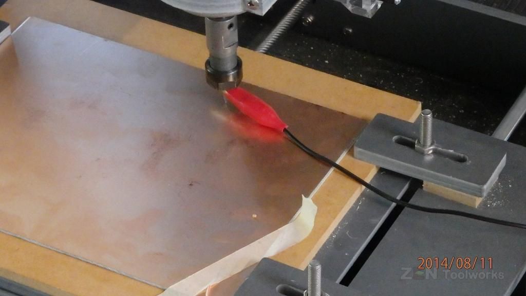
Probe Setup
- Now that our probe is set up you can then load your G-Code right on to the Chilipeppr workbench by locating your file and dragging it right onto the browser.
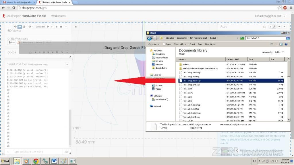
- Now we should see a representation of our object right on the Chilipeppr workbench!
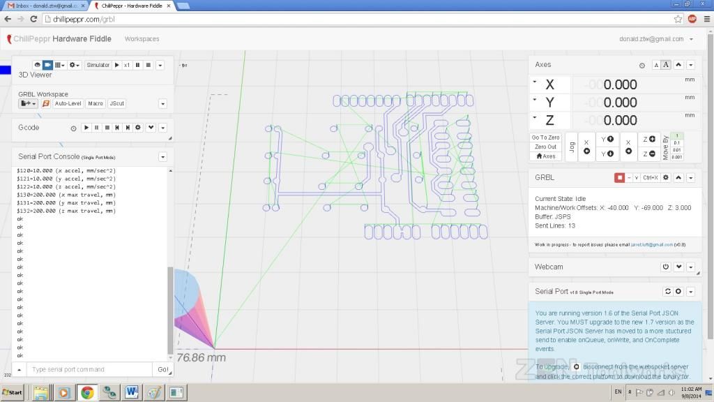
- You can do all sorts of adjustments, this online program allows you to move the camera around in a 3-D environment. But for now we are just going to be using the on-board Autoleveller. You can start this by clicking on the Auto-Level button on the top right corner of the workbench.
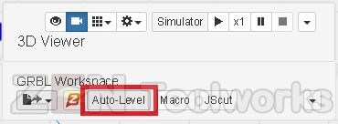
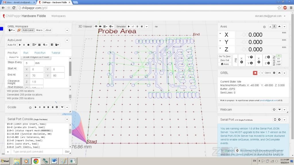
- Now we will get a new toolbox that has a lot of options for our auto-leveling. We want to press the Auto-Fill button then adjust the size of what you are probing and how many probes you want if necessary. Also adjust feed rate to adjust how fast you want your probe to touch the copper. All of the points will be shown by the program in a dot array right on the screen.
- You may want to set a higher clearance height and probe distance to be sure to have enough clearance for your copper.
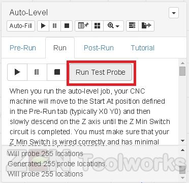
- Now we want to click on the Run tab then click on Run Test Probe. We want to make sure our probe works properly.
- If you want, you can just enter G38.2 Z-10 F20 to do the exact same thing a bit quicker.
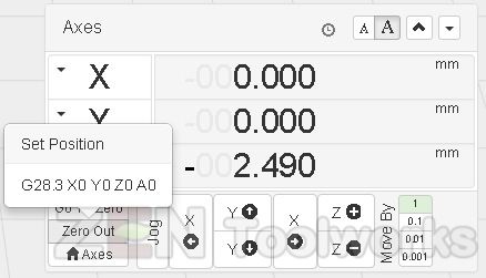
- Once you have a successful probe, the key being that you touch the copper without crashing the bit, press “Zero Out” on the Axis toolbar and you can now start the real thing.
- You can also disconnect the lead wire and simply touch the copper after pressing Run Test Probe if you are afraid of crashing the bit.
Probe Begin!
- You can now press the Run button.
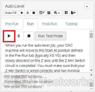
- You will trigger a warning about crashing your bit if you aren’t careful and didn’t wire your probe correctly. If you had followed all of the steps up to this point you should be fine and you can click “Let’s Get Probing”.

- It will now probe out your board and show you the imperfections in real time and in 3-D. Also it shows exaggerations of what is actually on your board that you can adjust.
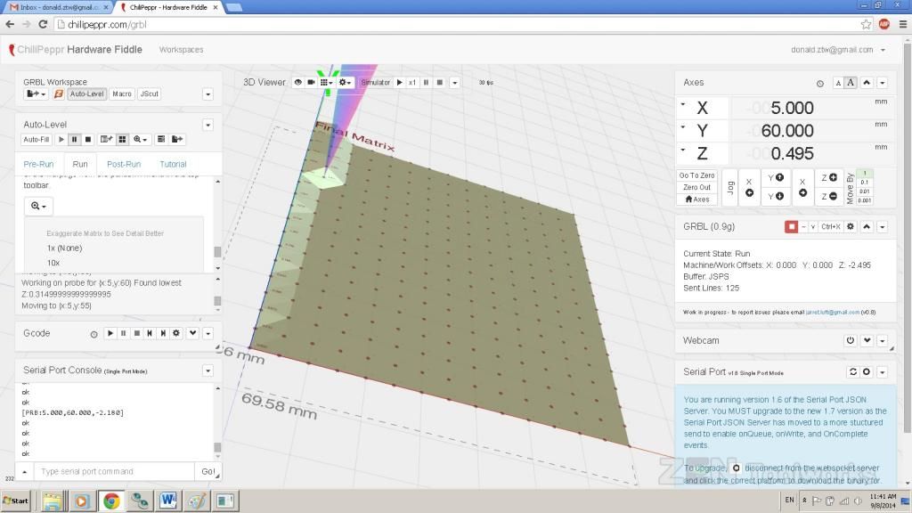
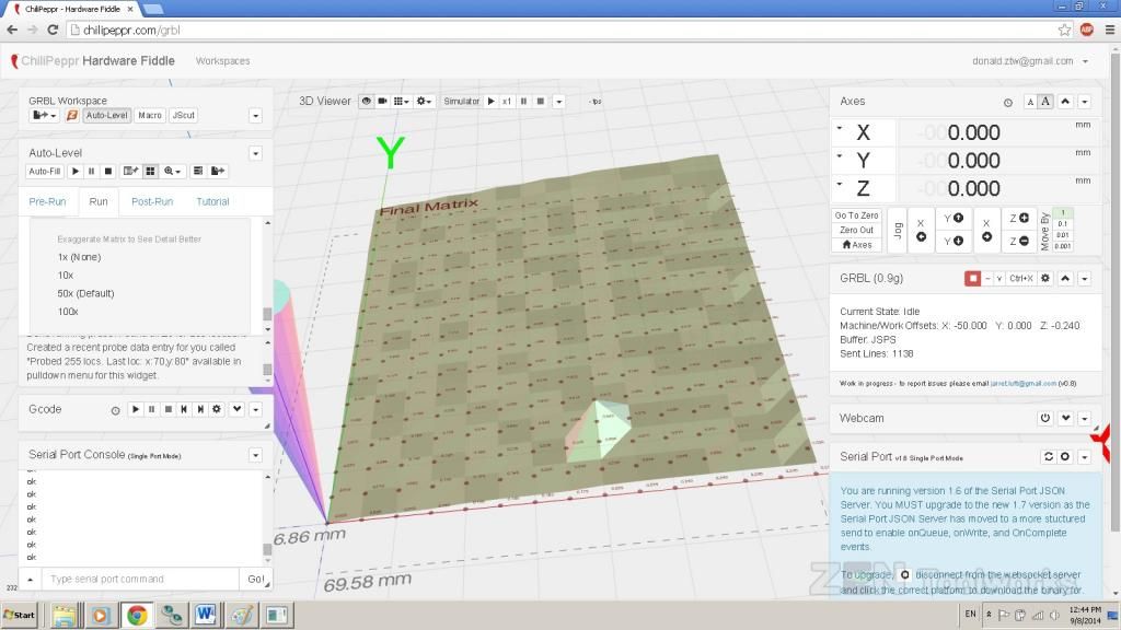
- Once our probe is done it will show a complete 3-D render of our board and all of it’s imperfections.
- And now you can view the modified code that was automatically done with the findings of our board. You go to the Post-Run tab and click “Send Auto-Levelled Gcode to Workspace”.
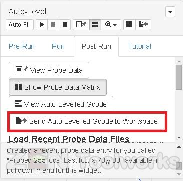
- Now you can view your GCode and Chilipeppr makes notes of all of the Z axis changes that occurred due to the probe.
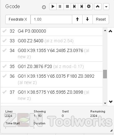
Milling Out the New GCode
- With our modified GCODE in hand we now can etch out our board. The first thing we need to do is send the bit back to X: 0 and Y: 0.
- Next we need to remove the probe from the bit and if able, remove the ground lead from the copper.
- Turn on your spindle. Make sure to wear eye protection for this part.
- Start up the new GCode and watch the machine mill out the board right before your eyes.
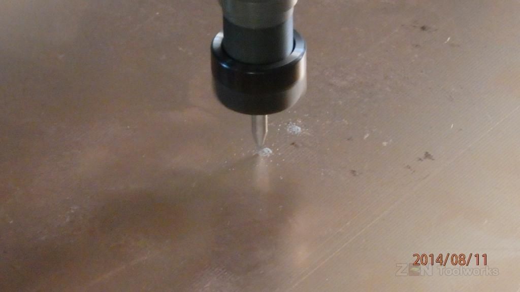
- After this all that is needed to do is drill and cut out your board and you are finished!