USB PCB Business Card

.JPG)


This is a business card that will type out some text when you plug it into a USB port.
It uses a ATtiny85 microcontroller with V-USB based code to emulate a keyboard. The typing is triggered by the CAPS LOCK status LEDs being toggled 3 times.
This instructable will focus on using CadSoft EAGLE to create your own USB PCB business card. I want you to be creative in the design, so some minor steps I've taken may have been omitted.
Code download is provided on step 8.
Circuit
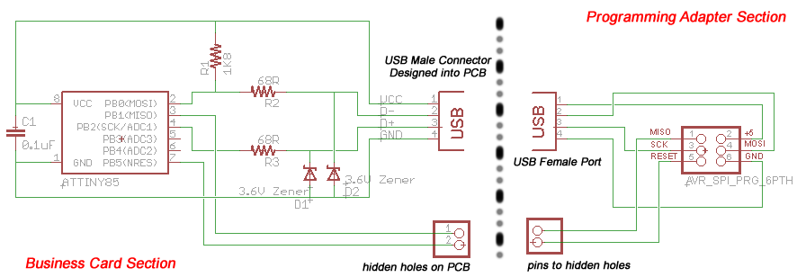
The circuit is based on V-USB's recommended circuitry. It's powered by the 5V from the USB port. There's two 68 ohm resistors, one on each of the USB data lines, these act as terminating resistors which suppress reflected signals. There is a 1.8 kilo ohm resistor on the D+ line, which allows the computer to detect when something connects to the USB port, and it identifies the device as a low speed device. Two Zener diodes with Vz of 3.6V are on the data lines to clamp the voltage on those lines. There is a 0.1 uF capacitor between the 5V and GND as a decoupling capacitor.
Since the business card should be a compact and thin design, 0604 surface mount packaging is selected for most of the components. The diodes are Mini MELF packaging (they look cool in my opinion).
The microcontroller is an ATtiny85, which is a 8 pin AVR microcontroller. The SOIC package version is chosen to keep the design compact and thin.

To program the microcontroller, in-circuit serial programming is used, which requires the signals: reset, SCK, MOSI, MISO, along with power and ground. The SCK and MOSI are exposed by the USB connector, while two pads are provided for the MISO and reset signals. This allows for a programming adapter to be made.
USB Connector

This connector will be a USB male "A" connector, which plugs into a USB female "A" port (the kind found on computers). First, measurements are taken from the USB port. I create an Eagle component with the dimensions (you need to create a library file first), and also place the pads. It is important to use pads because Eagle will remove the soldermask from pad areas by default. We need the pads to be exposed (not covered by soldermask) in order to make a connection with the USB port.
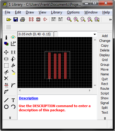
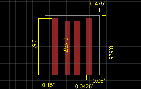
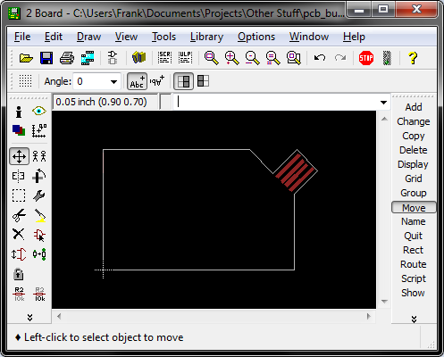
The created connector component is placed onto the PCB layout. The dimension layer must be a continuous line that follows the outline of the business card and the connector. The dimension layer is what the manufacture will follow when milling your PCB outline.
Layout


Layout the component as shown, or you can be creative, as long as your layout matches the circuit. For low speed USB, you don't have to worry too much about how the traces are layed out. For high speed designs, you should try to keep the differential D+ and D- signals together and away from noise, but our design is low speed.
Make it look nice! Personally, I like seeing symmetry, parallel or perpendicular angles, and even spacing, but that's my personal preference. You might like curves, abstractness, and chaos. This is all personal preference.
Artwork
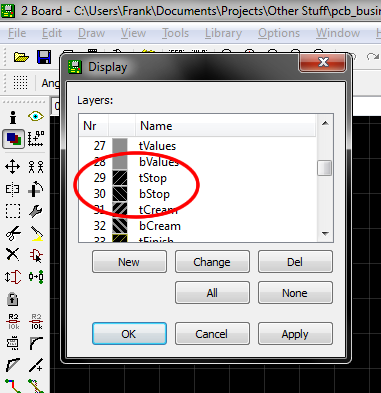
The tStop and bStop layers in Eagle control the soldermask. Soldermask will not be present on the areas covered by tStop or bStop. The "t" and "b" mean "top" and "bottom. This fact can be used to your advantage.
Remember that areas with copper and soldermask will look light green, areas with no copper but with soldermask will look dark green, areas with no copper and with no soldermask will look sort of yellowish. Also remember that more light will go through if the bottom layer is uncovered.
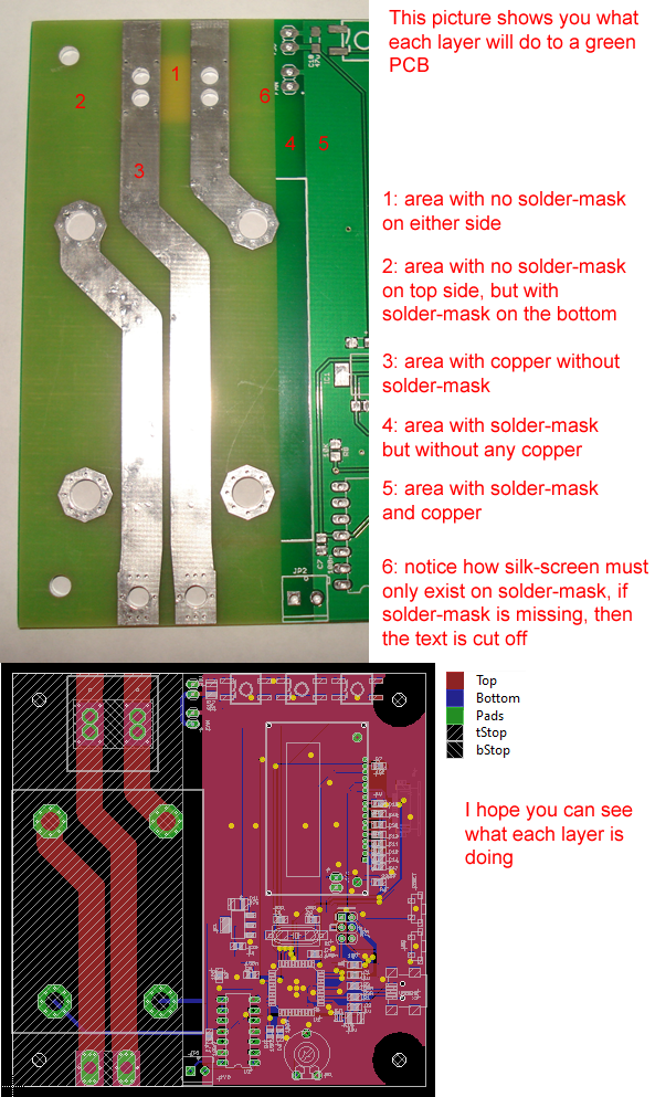
Area with no soldermask but with copper will become tinned. This will be silver if you get your board tinned with regular tin or lead solder. If you want to spend more money, you can ask the PCB manufacture for gold plating instead.
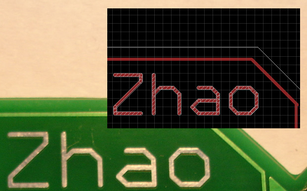
On my own card, you can see that I've placed my own name in both the top copper layer and the tStop layer, thus creating the silver text effect by placing text under an area without any soldermask.
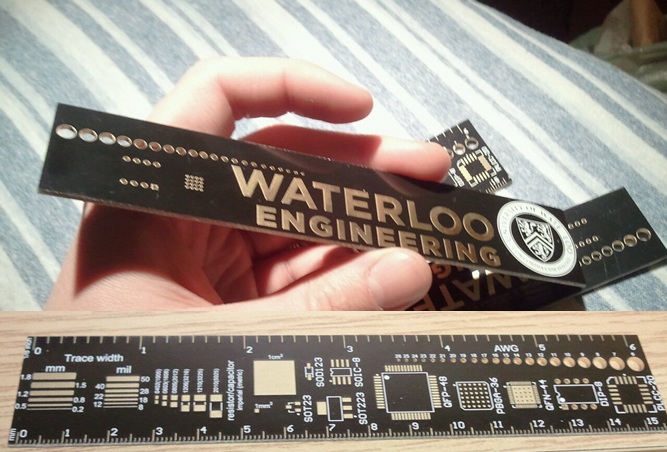
You can also ask the manufacture for other colours aside from green. Here is my friend's University of Waterloo PCB Ruler, created with black solder mask and gold plating (black and gold are my school's colours):
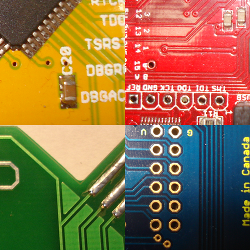
Here are some other possible PCB colour combinations:
Silk screen is the layer usually used for text, it goes over the soldermask. It is usually specified using the "tSilk" and "bSilk" layers in Eagle. It is important to remember that silk screen cannot exist without being on top of soldermask. You can usually ask the manufacture for a specific silk screen colour, the default is usually white silk screen with green soldermask.
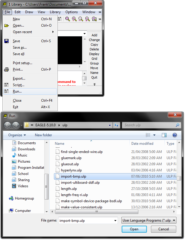
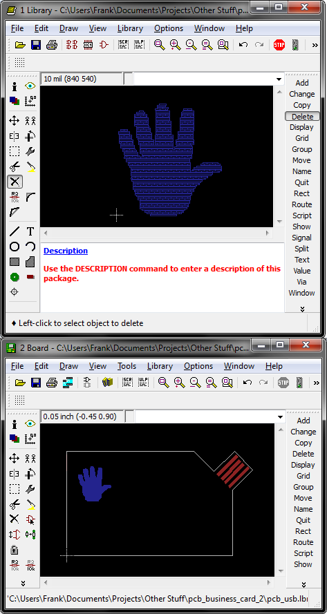
Another neat trick is to import bitmap images as components so you can have bitmaps on your PCB, you can do this for any of the layers. Create a component in a library file, and then run the user script called "import-bmp". Save the library and add the component to your PCB.
Manufacturing the PCB

Seeed Studio offers a service that can get me 10 pieces for $28 plus shipping, and it takes 5 days to manufacture, plus shipping time. I think this is an extremely good deal.
I have a CAM job (see attached) that you need to load into the CAM processor inside Eagle, running this CAM job will generate a collection of PCB Gerber files that you need to send to Seeed Studio (or another company) in order to get your PCB manufactured. Zip up the file, and email them to the company (after you pay).
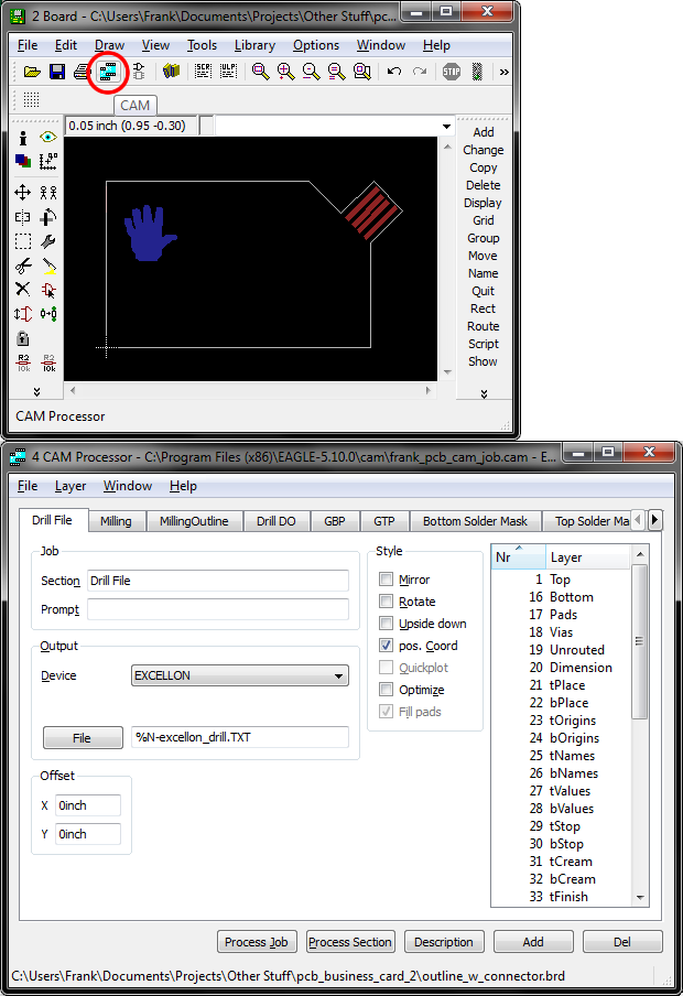
Please be aware of the file that your bitmap layer goes into! If you select the bitmap layer in the copper gerber file, then the bitmap will become a part of the PCB's copper. If you select the bitmap layer in the silkscreen gerber file, then the bitmap will become a part of the PCB's silkscreen.
Please use a Gerber file previewing tool before sending it off to manufacturing. I personally use Gerbv http://gerbv.sourceforge.net/
For kicks, I also made some non-USB business cards/keychains, see picture above (I forgot why I blurred the picture). The smaller size made these dirt cheap.
Downloads
Fixing the Connector


Ideally you want 2.4mm thick PCB material, but apparently this costs extra, so the default 1.6mm was used. The USB connector needs to be thicker than 1.6mm so green electrical tape was applied to the back of the connector to add some thickness to it. See above diagram for my technique for applying the tape.
Circuit Assembly
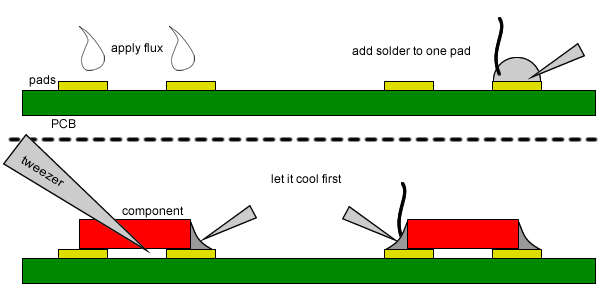
Solder all of the electrical components. 0604 sized components are very easy to solder if you have a pair of tweezers.
Put some solder on one pad, keep heating that pad and move the component into that pad, make sure it's aligned correctly, then remove the heat and let the first joint cool. Then you are able to solder the 2nd joint very easily.
Remember, flux can make the difference between a fun project and quitting the electronics hobby. I suggest you get a flux pen.
Programming the AVR
Open up the file "main.c" and find the place where the string is stored, look for the function "puts_P". You need to edit this string before compiling (or else it will print my text instead of yours). You'll notice that the string is stored in flash memory, and if you compile a longer string, the size of the flash compilation increases. Please be advised that you cannot exceed the memory capacity of the ATtiny85, which is 8KB of flash memory.
After editing the string, compile the code. The ".avrproj" file is a file format that can be opened by AVR Project IDE (a IDE I made for myself), which makes compiling the project very easy.
A hex file is generated and you can write the hex file into the AVR. You need an AVR programmer of some kind, and connected to the business card as shown in the schematic below. Remember to connect those hidden connections!
Also please note that the programmer must be set to use a low speed due to the 68 ohm resistors on the D+ and D- signals. This means the AVRDUDE option "-i <delay>" must be included, so the command looks something like: "avrdude -c programmer_name -p attny85 -i 100 -U flash:w:file_name.hex"
How do you connect the programmer? First take a look at the schematic:

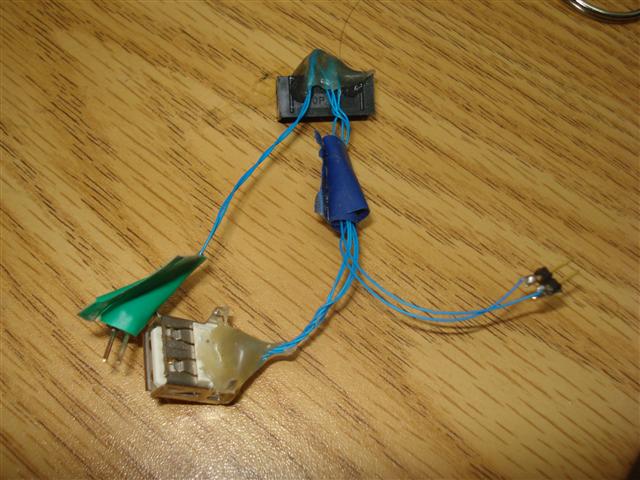
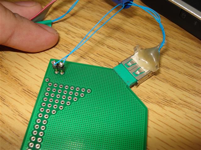
I made a not-so-neat looking programming adapter using a USB port, a AVR ISP connector, and some wire:
Here it is, connected to my USBtinyISP:
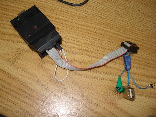
This is what the card looks like while being programmed:
Downloads
Explaination of the Code
The code uses V-USB to create a USB keyboard. V-USB is a software package that allows you to make USB devices out of AVR microcontrollers.
Instead of explaining using text, I have a video tutorial about how to build a USB keyboard:
http://www.frank-zhao.com/index.php?page=usnoobie_rfid_keyboard
Please note that this two part video is over 15 minutes in total. I've put an incredible amount of effort into the video. Please watch it in 720p full screen so you can read all the text.
I also have another Instructable that will explain more USB and V-USB stuff to you: https://www.instructables.com/id/USB-Wii-Classic-Controller/
The differences between the RFID USB Keyboard and this USB PCB Business Card is that the ATtiny85 is used instead, and the text comes from internal flash memory instead of a serial port. One important aspect to note is the fact that the ATtiny85 uses an internal PLL to generate the clock speed that V-USB requires.
Also read my other USB instructable involving creating more USB devices, where I explain the USB bus, descriptors, and other aspects in more detail.
Using the Card
Plug into an USB port, making sure that the pads on the card will connect with the contacts inside the USB connector.
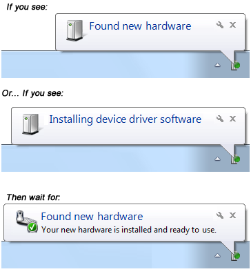
Your operating system may start install a driver automatically, if this happens, wait for it to finish installing.
Open a text editor such as "Notepad".
Press CAPS-LOCK on your keyboard a few times.
Watch the magic happen as the card types out text into the text editor.
What if it doesn't work
Did you try taking it out and plugging it back in?
Did you plug it in right-side-up? Follow this diagram:

If CAPS-lock doesn't trigger it, then try NUM-lock and scroll-lock (this seems to be a problem with Linux).
If it causes your computer to act weird after unplugging the card, just hit both of your shift keys a few times. This should only be a problem if you unplug the card before it finishes typing, because it may have "held down" the shift key.